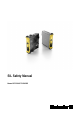
SIL Safety Manual Manual SCS 24VDC P1SIL3DS
Revision History Version Date Change 0.0 05/2012 First Edition 1.0 08/2015 Page 13, chapter 6.2 updated 2.0 06/2017 Page 5, TÜV logo updated Page15, deleted Contact Address Weidmüller Interface GmbH & Co. KG Klingenbergstraße 16 32758 Detmold Germany Phone +49 (0) 5231 14-0 Fax +49 (0) 5231 14-292083 info@weidmueller.com www.weidmueller.
Content Content Revision History ............................................................................................................................................... 3 Contact Address ............................................................................................................................................... 3 Content ............................................................................................................................... 4 1. Scope and standards ......
Scope and standards 1. Scope and standards 1.1 Scope 1.2 This safety manual applies to SIL3 relays from Weidmüller's SAFESERIES for the following items produced after 03/2012: SCS 24VDC P1SIL3DS SCS 24VDC P1SIL3DS M SCS 24VDC P1SIL3DS MG3 1303890000 1303760000 1304040000 SIL3 relays in the SCS 24VDC P1SIL3DS series from Weidmüller Interface GmbH & Co KG Klingenbergstrasse 16 32758 Detmold Germany have been certified by TÜV NORD CERT GmbH Am TÜV 1 30519 Hannover Germany according to EN 61508 SIL3.
Scope and standards FMEDA (Failure Mode, Effects and Diagnostic Analysis): Systematic way to identify and evaluate the effects of different component failure modes, to determine what could eliminate or reduce the chance of failure, and to document a system in consideration. MTTF (Mean Time To Failure): Mean time between two failures. MTTF is a basic measure of reliability for non-repairable systems.
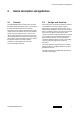
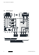
Device description and application 2. Device description and application 2.1 General Our SAFESERIES line of safety relays are used for safety-related shutdowns (DTS = de-energized to safe) of facilities in the process industry. All products in this series comply with the requirements found in EN 61508, SIL 3 for “low demand mode” and “high demand mode”. The “M” and “M G3” types also feature a monitoring circuit for receiving signals from the field.
Device description and application 2.
Notes on configuring 3. Notes on configuring 3.1 Low demand mode of operation The SIL3 relays from the SAFESERIES are used in low demand mode, when their demand frequency is no more than five times per year and no more than double the repeated testing frequency (refer to DIN EN 61508-4, 3.5.12). The corresponding parameter is the value -6 PFDavg = 3.07 ⋅ 10 , which is valid for a testing interval Tproof of 12 years. 3.
Mounting and installation 4. Mounting and installation The operating instructions for the SIL3 relay with the order number IS SCS 24VDC P1SIL3DS 1345290000 must be made available. The instructions, constraints and limitations contained in these instructions must be taken into consideration when installing and operating the SIL3 relay. The output circuit is protected with a miniature device fuse (GS fuse). The fuse is accessible on the front side of the housing.
Periodic inspections 5. Periodic inspections Periodic functional inspections are used to discover non-visible and dangerous faults which cannot be detected by the self-diagnostics. It is therefore important to check the functionality of the SIL3 relay with the proper frequency. The inspections should be carried out so that the flawless operation of the safety functions in conjunction with components can be proven. The operator must determine the type of tests and the proper time intervals.
Periodic inspections 5.1 Functional check Active input circuit • Apply U1 = 21.6 V DC to the connection terminals A1(+) and A2(-) ◊ The current consumption is I1 = 35 to 44.
Technical safety values 6. Technical safety values 6.1 Assumptions • The monitoring circuit is used exclusively for detecting field signals and responding to the control unit throughout the range 24 to 230 V UC. The monitoring circuit should not be used for technical safety-critical operations. • The environmental conditions correspond to the average industrial environment. • The specifications in the data sheet and the operating instructions should not be exceeded. • The max.
Technical safety values 6.2 Safety data Safety basic data Safety category SIL3 Safety standard DIN EN 61508 Device type A HFT 2 Tproof in years 12 Safety parameters “low demand mode” Frequency of demands 5 per year Part of architecture 1oo1 1oo3 -6 -6 λDD in FIT 1.31 ⋅ 10 0.00 1.75 ⋅ 10 λDU in FIT 0.03 1.00 λSD + λSU in FIT 188.97 1.00 λTotal in FIT 189.00 2.00 SFF in % 99.98 50.00 PFDavg 0.00 -6 3.
1373930000/02/06-2017 15
Weidmüller Interface GmbH & Co. KG Klingenbergstraße 16 32758 Detmold Germany Phone +49 (0) 5231 14-0 Fax +49 (0) 5231 14-292083 info@weidmuller.com Order number: www.weidmueller.