
User Documentation


6 2555600000/02/05-2018
Intended use and device description
2.1 Intendes use
The safety relay SCS 24VDC P1SIL3 I serves the
purpose of safety-related switch-o of process in-
dustry systems (DTS = de-energised to safe).
The safety relay is intended to be used together
with Triconex® safety controllers from the Schnei-
der Electric company. A certicate of compatibility
is available for the systems Tricon™, Trident™ and
Tri-GP™.
The device fulls the safety integrity level 3 (SIL 3)
for low and high demand modes of operation ac-
cording to EN 61508.
2.2 Device description
The input of the safety relay uses a test pulse lter
and three relays connected in parallel. The re-
lay contacts in the output are connected in series.
Therefore, the safety-related switch-o is ensured
even in case of sticking contacts. The relay contact
circuit at the connection terminals 13 and 15 is pro-
tected against overload and short-circuit with a 5 A
fuse.
Connection terminals 14 and 15 are to be used for
implementing external fusing.
Connection terminals T1 and T2 must only be used
for checking the relay contacts. In order to do this,
the device must be released and the test current
must be limited to max. 500 mA.
The front of the device features a status LED
“RELAY OUTPUT”. The LED lights yellow when the
input circuit (connection terminals A1 and A2) of the
device is actuated.
The status LED does not indicate the electri-
cal switching state at the device output.
The status change at the device output is
executed with a certain delay after the status
LED indication has changed.
2 Intended use and device description
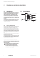
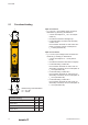
2.3 Block diagram
15
14
13
T1
T2
A
1
A
2
Logic
T5AL250V
+24 V
0 V
RELAY
OUTPUT