SIL Safety Manual Manual Safety Relay SCS 24VDC P1SIL3DS I
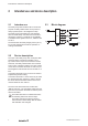
Content 1 Scope and definitions.................................... 4 1.1 Scope............................................................... 4 1.2 Terms and abbreviations.................................. 4 2 2.1 2.2 2.3 Intended use and device description........... 6 Intendes use..................................................... 6 Device description............................................ 6 Block diagram................................................... 6 3 3.1 3.2 3.3 3.
Scope and definitions 1 Scope and definitions 1.1 Scope This safety manual applies to the safety relay SCS 24VDC P1SIL3 I 2500980000 from the Weidmüller SAFESERIES product family.
Scope and definitions Device type A (simple subsystem): The failure modes of all constituent components are well defined and the behaviour under fault conditions can be completely determined. FMEDA (Failure Mode, Effects and Diagnostic Analysis): Systematic way to identify and evaluate the effects of different component failure modes, to determine what could eliminate or reduce the chance of failure, and to document a system in consideration.
Intended use and device description 2 Intended use and device description 2.1 Intendes use The safety relay SCS 24VDC P1SIL3 I serves the purpose of safety-related switch-off of process industry systems (DTS = de-energised to safe). The safety relay is intended to be used together with Triconex® safety controllers from the Schneider Electric company. A certificate of compatibility is available for the systems Tricon™, Trident™ and Tri-GP™.
Notes on configuration 3 Notes on configuration 3.1 Low demand mode of operation The safety relay is used with a low demand rate (low demand mode) when the demand rate of the relay does not exceed 5x per year and when it does not exceed double the frequency of the repeat test (proof test). The associated technical parameter is the value PFDavg that applies to the duration of the test interval Tproof. 3.3 A safe failure is not able to render a technical safety system dangerous or non-functional.
Commissioning and maintenance 4 Commissioning and maintenance The following operating instructions must be available for the safety relay. Designation: IS SCS 24VDC P1SIL3DS I Order number: 2530250000 It contains notes, boundary conditions and limit values that must be factored into the installation and operation of the safety relay. The safety relay must be checked for proper functioning prior to commissioning and after every change in wiring, see chapter 5.1 „Functional testing“.
Proof test 5 Proof test The purpose of the proof test is to detect any dangerous faults that cannot be detected by means of self-diagnostics. Therefore, the functionality of the safety relay must be tested in appropriate intervals. The selection of the type and intervals of the tests is the responsibility of the operator. The test intervals are, among other factors, determined by the calculation of each individual safety circuit in a system (PFD values).
Proof test 5.1 Functional testing Input circuit active • U1 = 24 V DC, input voltage at the connection terminals A1(+) and A2(-) is switched on ○○ current consumption is I1 = 45...
Technical safety values 6 Technical safety values Safety basic data Safety category SIL 3 Safety standard EN 61508 Device type A HFT 2 Tproof in years 12 Safety parameters “low demand mode” Frequency of demands 5 per year λDD in FIT 0 λDU in FIT 0.4 λSD + λSU in FIT 1936.2 λTotal in FIT 1936.6 SFF in % 50 PFDavg (complete) 4.
Technical safety values 12 2555600000/02/05-2018
www.weidmueller.com Weidmüller Interface GmbH & Co. KG Klingenbergstraße 16 32758 Detmold Germany T +49 5231 140 F +49 5231 14292083 www.weidmueller.