
User Documentation

RSV VERT - Current distributor module
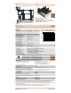
Schematic Assembly
Ordering data
Type Order No.
RS VERT 8P 24VDC Z UL V1 2727410000
Technical data
Rated data
Operating voltage ⎓ 24 ± 25% Vdc
Max. total current 76,5 A
Environmental conditions
Operating ambient temperature -25…+60 ºC
(4)
Storage ambient temperature -25…+60 ºC
Max. operating humidity 85% non-condensing
Rated insulation voltage 50 Vac / 70 Vdc
Surge voltage category II
Pollution severity level 2
Insulation test voltage (1min) 0,86 kVac / 1,22 kVdc
General information
Dimensions (Lenght x Width x Height) 102 x 108,2 x 78,2 mm
DIN rail (vertical / horizontal) TS32, TS35
IPC-A-610 Class (PCBA) Class 2 — Dedicated Service Electronic Products
Fuse-links to be used (acc. UL)
(3)
- SIBA 179021.4: 250 Vac / 4 A - Fast acting miniature fuse-link 5x20mm
- SIBA 179021.5: 250 Vac / 5 A - Fast acting miniature fuse-link 5x20mm
- SIBA 179021.6,3: 250 Vac / 6,3 A - Fast acting miniature fuse-link 5x20mm
- SIBA 179021.8: 250 Vac / 8 A - Fast acting miniature fuse-link 5x20mm
- SIBA 179021.10: 250 Vac / 10 A - Fast acting miniature fuse-link 5x20mm
CAUTION: In case of a fuse-link replacement, the following procedure applies:
1. Identify the broken fuse signalized by the red light
2. Switch off the power supply of the module
3. Dismount the fuse-holder cap by means of a screwdriver
4. Remove the broken fuse inside
Standard approvals
Safety Requirements for Electrical Equipment for Measurement,
Control, and Laboratory Use. Part 1: General Requirements
Safety Requirements for Electrical Equipment for Measurement,
Control, and Laboratory Use. Part 2-201: Particular Requirements
for Control Equipment
Telcordia GR-63-CORE Seismic Zone 4
RoHS 2011/65/EU EN 50581
EMC immunity requirements for industrial applications IEC 61326-1
Immunity to conducted disturbances, induced by radio-frequency
fields
DIN EN 61000-4-6
Surge immunity test
DIN EN 61000-4-5
(2)
Electrical fast transient/burst immunity test
DIN EN 61000-4-4
Electrostatic discharge immunity test DIN EN 61000-4-2
Notes:
Weidmüller t
D-32758 Detmold
Insulation coordination (IEC/UL61010-1 and IEC/UL61010-2-201)
Current derating diagram
Max. current per channel 9,5 A
*See derating diagram
Relay contact power (min. / max.) 1 V @ 1 mA / 30 V @ 150 mA, Resistive
Input Connector: 1988600000 - LUF 10.00/02/90 5.0SN BK BX [tampoprinted]
Clamping range (min / max) 0,5 mm2 - AWG20 / 16 mm2 - AWG6
Cable stripping length 18 - 21 mm: depending on the selected ferrule
Output Connector: 1331260000 - LMF 5.08/11/180 3.5SN OR BX [tampoprinted]
Clamping range (min / max) 0,12 mm2 - AWG 24 / 2,5 mm2 - AWG 12
Cable stripping length 10 - 12 mm: depending on the selected ferrule
Order No.
5. Insert a replacement fuse of the correct ratings
6. Close the fuse-holder cap again by means of a screwdriver
2780760000
2780750000
2780740000
2780730000
2780640000
7. Reconnect the power supply of the module
8. Ensure that the identified green light has turned on
Approvals of the fuse-links: IEC/EN 60127-2/1, VDE 0820-2/1, UL File No.E167295
IEC/UL61010-1, CSA-C22.2 NO. 61010-1-12
IEC/UL61010-2-201, CSA C22.2 NO. 61010-2-201:18
2730100000/06/10.2020
1) This product is intended to be used in fixed installations inside an enclosure or electrical cabinet with a protection degree IP54 minimum.
2) In case of using a power supply with earth connection, the cable length of the output channels must be limited up to 30 meters.
3) If the equipment is used without non-specified fuse-links or in a manner not specified (ex:switch on/off during operation), the protection provided
by the equipment may be impaired.
4) When fuse-links with different current ratings are used in the same module, the lowest specified ambient temperature applies.
5) The safety of any system incorporating the equipment is in the responsability of the assembler of the system.
Current distributor interface with 8 channels, fuse status indicator, and
alarm contact. Protection by 5x20mm fuse-links.
Monitorization of each fuse status.
• Visual: Normal operation of the fuse (Green) / Broken fuse (Red).
• Remote: If all fuses in normal operation 11-14 continuity. If one of the
fuses fail 11-14 open circuit.
- Fuse-links are not delivered with the product.
Control
circuit
0
1
2
3
4
5
6
7
8
9
10
0 5 10 15 20 25 30 35 40 45 50 55 60 65
Channel current in A
Operating temperature in ºC