
User Documentation

Title: PROtop IO-Link Register Description
2019.11.29, Page 10/17
DocVersion: 1.1
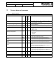
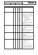
Table 3: Parameters for PROtop IO-LINK
Name
Type
Length
Access
Index
Comment/ Description
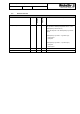
PROtop LED Control Select
Bool
1 byte
RW
304
Selects the control for LEDs ON/FAIL and ATTN
on PROtop
0 = LED control by PROtop
1 = LED control by IO-LINK
Default value = 0
This parameter is only valid, if “PROtop Configu-
ration Select” = 0x01. Otherwise the default
value is used.
The parameter is active after restart.
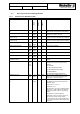
PROtop On Fail State Read
ENUM
8 Bit
R
305
This register shows the current state of the LED
ON/FAIL on PROtop. The bits are defined as the
following:
bit 0 or all bits = 0 - Green off and Red off
bit 1 - Red on
bit 2 - Green on
bit 3 - Red slow flashing
bit 4 - Green slow flashing
bit 5 - Red flashing
bit 6 - Green flashing
bit 7 - Red - Green slow flashing
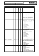
PROtop On Fail Behavior Set
ENUM
8 Bit
RW
306
With this register the state of the LED ON/FAIL
on PROtop can be controlled. The bits are de-
fined as the following:
bit 0 or all bits = 0 - Green off and Red off
bit 1 - Red on
bit 2 - Green on
bit 3 - Red slow flashing
bit 4 - Green slow flashing
bit 5 - Red flashing
bit 6 - Green flashing
bit 7 - Red - Green slow flashing
This parameter is only valid, if “PROtop LED
Control Select” = 0x01.
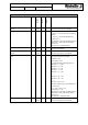
PROtop LED Attn State Read
ENUM
8 Bit
R
307
This register shows the current state of the LED
ATTN on PROtop. The bits are defined as the
following:
bit 0 or all bits = 0 - Yellow off
bit 1 - Yellow on
bit 2 - Yellow slow flashing
bit 3 - Yellow flashing
PROtop LED Attn Behavior Set
ENUM
8 Bit
RW
308
With this register the state of the LED ATTN on
PROtop can be controlled. The bits are defined
as the following:
bit 0 or all bits = 0 - Yellow off
bit 1 - Yellow on
bit 2 - Yellow slow flashing
bit 3 - Yellow flashing This parameter is only
valid, if “PROtop LED Control Select” = 0x01.