PROtop IO-Link Register Description The contents of this document are proprietary to Weidmüller and shall not be disclosed, disseminated, copied or used, except for purposes expressly authorized in writing by Weidmüller
Title: PROtop IO-Link Register Description DocVersion: 1.1 2019.11.29, Page 2/17 Table of Contents 1 Introduction ..........................................................................................................................................3 1.1 Purpose..................................................................................................................................................3 2 Communication via IO-LINK ................................................................
Title: PROtop IO-Link Register Description DocVersion: 1.1 1 2019.11.29, Page 3/17 Introduction 1.1 Purpose This document describes the use of the PRO COM IO-LINK module with the PROtop communicative Power Supply.
Title: PROtop IO-Link Register Description DocVersion: 1.1 2 2019.11.29, Page 4/17 Communication via IO-LINK 2.1 Configuration of PRO TOP IO-LINK system For the configuration of PROtop IO-LINK the following points should be note: ➔ The Function “Data Storage” is not supported and must be disabled in the engineering tool! ➔ Writing an invalid value into a writeable parameter register does not evoke an error.
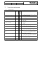
Title: PROtop IO-Link Register Description DocVersion: 1.1 3 2019.11.29, Page 5/17 Process data and parameter 3.1 Process data in Comment/ Description Length [Bit] Type Bit-Offset Table 1: Process data in for PROtop IO-LINK Parameter PROtop - Output Voltage INT16 40 16 Output voltage value in cV (1000 = 10.00V) on DC- Output after O-ring MOSFET (on terminal). PROtop - O-Ring Voltage INT16 24 16 Output voltage value in cV (1000 = 10.00V) on DC- Output before O-ring MOSFET.
Title: PROtop IO-Link Register Description DocVersion: 1.1 3.2 2019.11.
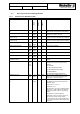
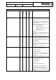
Title: PROtop IO-Link Register Description DocVersion: 1.1 3.3 3.3.1 2019.11.29, Page 7/17 Non-cyclical I/O data of PROtop IO-LINK Parameters for PROtop IO-LINK Type Length Access Index Table 3: Parameters for PROtop IO-LINK Name PROtop Over Voltage Peaks Counter U16 2 bytes R 257 Number of “PROtop - Over Voltage Peaks Failed” events since production of the PROtop. PROtop Device Temperature S16 2 bytes R 260 Internal temperature (heat sink at rectifier of PROtop) in cC° (1000 = 10.00°C).
Title: PROtop IO-Link Register Description DocVersion: 1.1 2019.11.29, Page 8/17 Table 3: Parameters for PROtop IO-LINK Index Comment/ Description Access Type Length Name PROtop Reverse Voltage Output Counter U16 2 bytes R 289 Number of “PROtop - Reverse Voltage Output” events since production of the PROtop.
Title: PROtop IO-Link Register Description DocVersion: 1.1 2019.11.
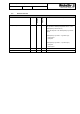
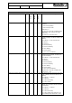
Title: PROtop IO-Link Register Description DocVersion: 1.1 2019.11.29, Page 10/17 Table 3: Parameters for PROtop IO-LINK PROtop LED Control Select Bool 1 byte Index Comment/ Description Access Type Length Name RW 304 Selects the control for LEDs ON/FAIL and ATTN on PROtop 0 = LED control by PROtop 1 = LED control by IO-LINK Default value = 0 This parameter is only valid, if “PROtop Configuration Select” = 0x01. Otherwise the default value is used. The parameter is active after restart.
Title: PROtop IO-Link Register Description DocVersion: 1.1 2019.11.29, Page 11/17 Table 3: Parameters for PROtop IO-LINK PROtop DI Control Select Bool 1 byte Index Comment/ Description Access Type Length Name RW 309 Selects the control for Digital Input/ Output on PROtop 0 = DI control by PROtop 1 = DI control by IO-LINK Default value = 0 This parameter is only valid, if “PROtop Configuration Select” = 0x01. Otherwise the default value is used. The parameter is active after restart.
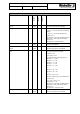
Title: PROtop IO-Link Register Description DocVersion: 1.1 2019.11.29, Page 12/17 Table 3: Parameters for PROtop IO-LINK Index Comment/ Description Access Type Length Name PROtop DC Not OK Counter U16 2 bytes R 321 Number of “PROtop - DC not OK” events since production of the PROtop. PROtop DC Lower Threshold float 4 bytes R, W 322 This register defines the Lower Threshold for the “DC not OK” detection. It is given in percent of configured output.
Title: PROtop IO-Link Register Description DocVersion: 1.1 2019.11.
Title: PROtop IO-Link Register Description DocVersion: 1.1 3.3.2 2019.11.29, Page 14/17 System Commands for PROtop IO-LINK Table 4: System Commands for PROtop IO-LINK Command Name Command Number Combi Restart Command Comment/ Description After the Communication IO-LINK device gets the command it fulfills a soft restart where the following steps are executed.
Title: PROtop IO-Link Register Description DocVersion: 1.1 3.3.3 2019.11.29, Page 15/17 Event Codes for PROtop IO-LINK In some engineering tools the event codes are prefixed with 0xFFFF. Table 1 Events Codes for PROtop IO-LINK PROtop - Over Voltage Peaks Failed 0x8CAC Information PROtop - Device Temperature >100°C 0x8CA1 Information Single shot Comment/ Description Length [Bits] Event Mode Event Type Event Code Event Name 1 bit Signals an Over Voltage Peak at the AC input of the PROtop.
Title: PROtop IO-Link Register Description DocVersion: 1.1 CIOL - Device Temperature >60°C 0x8CA7 2019.11.
Title: PROtop IO-Link Register Description DocVersion: 1.1 4 4.1 2019.11.29, Page 17/17 Special Functions Setting Control of PROtop via IO-Link The PROtop can be configured to operate at different modes. This can be changed with setting the “Configuration Select” parameter. Every time the parameter is written its necessary to perform a power cycle or execute the restart command for validation.