topGUARD IO-Link Addressing & Register Description The contents of this document are proprietary to Weidmüller and shall not be disclosed, disseminated, copied or used, except for purposes expressly authorized in writing by Weidmüller
Title: topGUARD IO-Link Register Description DocVersion: released 2020.02.17, Page 2/21 1.2 Table of Contents 1 Introduction ..........................................................................................................................................3 1.1 1.2 Purpose..................................................................................................................................................3 Abbreviations ..............................................................
Title: topGUARD IO-Link Register Description DocVersion: released 2020.02.17, Page 3/21 1.2 1 Introduction 1.1 Purpose This document describes the use of the PRO COM IO-LINK module with the topGUARD communicative electronic fuse. 1.
Title: topGUARD IO-Link Register Description DocVersion: released 2020.02.17, Page 4/21 1.2 2 Addressing the topGUARD station Before you start the commissioning work, the following requirements must be fulfilled: • The topGUARD station must be fully assembled and wired. • The power supply must be connected. 1.) Switch on power supply The electronic load monitors are switched off exworks.
Title: topGUARD IO-Link Register Description DocVersion: released 2020.02.17, Page 5/21 1.2 3 3.1 Communication via IO-LINK Configuration of top Guard IO-LINK system For the configuration of the top Guard IO-LINK the following points should be note: ➔ The Function “Data Storage” is not supported and must be disabled in the engineering tool! ➔ Writing an invalid value into a writeable parameter register does not evoke an error.
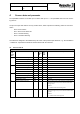
Title: topGUARD IO-Link Register Description DocVersion: released 2020.02.17, Page 6/21 1.2 4 Process data and parameter The topGUARD modules can be built up in a station with up to N < = 32 topGUARD electronic load monitoring devices. The process input data delivers an array of 4 Bit values, which represent the following states for each ELM device.
Title: topGUARD IO-Link Register Description DocVersion: released 2020.02.17, Page 7/21 1.2 TGD-ELM Short Circuit Switch Off Bool 1 1 Event, if switched off (tripping) the DC-Output of corresponding top Guard ELM Condition: tripping of ELM regarding selected tripping characteristic curve at Register “TGD-ELM Tripping Characteristic Curve Select” and tripping current limit at register “TGD-ELM Tripping Current Limit”.
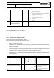
Title: topGUARD IO-Link Register Description DocVersion: released 2020.02.17, Page 8/21 1.2 S32 4 bytes R Index Access Length Type 258 Data Source/Sink Table 2 Parameters for topGuard IO-LINK Name Comment/ Description TGD ELM Output voltage in cV (1000=10.00V) on DC-Output of the corresponding ELM device.
Title: topGUARD IO-Link Register Description DocVersion: released 2020.02.17, Page 9/21 1.2 Bool 1 byte W Index Access Length Type 297 Data Source/Sink Table 2 Parameters for topGuard IO-LINK Name Comment/ Description TGD ELM Only valid at TGD-ELM State b011 (“fuse on” and "fuse switched off after short circuit") Otherwise it has no effect. TGD-ELM Reset Short Circuit Command [] After the ELM device receives the command, it resets the state “"fuse switched off after short circuit".
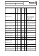
Title: topGUARD IO-Link Register Description DocVersion: released 2020.02.17, Page 10/21 1.2 U16 TGD-ELM Load Alarm Warning Value [] 2 bytes R W Index Access Length Type 327 Data Source/Sink Table 2 Parameters for topGuard IO-LINK Name Comment/ Description TGD ELM Sets the threshold of the current value in mA for the Load Alarm Warning state of the corresponding top Guard ELM.
Title: topGUARD IO-Link Register Description DocVersion: released 2020.02.17, Page 11/21 1.2 U16 2 bytes R W Index Access Length Type 328 Data Source/Sink Table 2 Parameters for topGuard IO-LINK Name Comment/ Description TGD ELM Sets the “TGD-ELM Tripping Current Limit” in mA of DC- Output of the corresponding ELM device.
Title: topGUARD IO-Link Register Description DocVersion: released 2020.02.17, Page 12/21 1.2 Bool 1 byte W Index Access Length Type 332 Data Source/Sink Table 2 Parameters for topGuard IO-LINK Name Comment/ Description TGD ELM Only valid at TGD-ELM State b001 (“fuse on”) or b011 (“fuse on” and "fuse switched off after short circuit") Otherwise it has no effect. After the corresponding ELM device receives the command, it sets the state "fuse off remote".
Title: topGUARD IO-Link Register Description DocVersion: released 2020.02.17, Page 13/21 1.
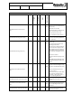
Title: topGUARD IO-Link Register Description DocVersion: released 2020.02.17, Page 14/21 1.2 Type Length Access Index Data Source/Sink Table 2 Parameters for topGuard IO-LINK Name FIM Device Serial Number String [15] 15 bytes R 7029 FIM Serial number of the FIM device. FIM Device HW Version String [8] 8 bytes R 7031 FIM Hardware version number of the FIM device. FIM Device SW Version String [8] 8 bytes R 7032 FIM Software version number of the FIM device.
Title: topGUARD IO-Link Register Description DocVersion: released 2020.02.17, Page 15/21 1.
Title: topGUARD IO-Link Register Description DocVersion: released 2020.02.17, Page 16/21 1.2 4.3.2 System Commands for topGuard IO-LINK Table 3: System Commands for top Guard IO-LINK Command Name Command Comment/ Description Number 160 Combi Restart Command FIM Restart Command CIOL Set Factory Default Command (1) Soft restart of all TGDELMs (2) Soft restart of the FIM (3) Soft restart of the CIOL 161 After the FIM device gets the command it executes a soft restart.
Title: topGUARD IO-Link Register Description DocVersion: released 2020.02.17, Page 17/21 1.2 4.3.3 Event Codes for topGuard IO-LINK In some engineering tools the event codes are prefixed with 0xFFFF. 6144 + N-1 Information Event Mode Event Type Event Code TGD-ELM - Over Voltage Peak Singleshot Length [Bits] Table 4 Events Codes for top Guard IO-LINK Event Name 1 bit Comment/ Description Signals an Over Voltage Peak at the corresponding ELM device.
Title: topGUARD IO-Link Register Description DocVersion: released 2020.02.17, Page 18/21 1.2 CIOL - Device Temperature >70°C 36322 Warning Appears / Disappears 1 bit Signals, that temperature on CIOL device exceeds 70°C. Condition: T > 70°C CIOL - Device Temperature <-25°C 36323 Information Singleshot 1 bit Signals, that temperature on CIOL device exceeds -25°C.
Title: topGUARD IO-Link Register Description DocVersion: released 2020.02.17, Page 19/21 1.2 5 Special Functions 5.1 Tripping Current and Warning Limit Values Configuration The TGD ELM can be configured to operate at different tripping current with 2 different characteristics (medium and lag time). The tripping current limit can only be configured to fix values matching the entries in the table.
Title: topGUARD IO-Link Register Description DocVersion: released 2020.02.17, Page 20/21 1.2 Switch off time in ms Warning limit default Prewarning (Alarm1): Table 6: Tripping characteristic lag TGD ELM-6 Current (I) Current (I) Current (I) Current (I) in A in A in A in A 1A Range 2A Range 3A Range 4A Range Current (I) in A 5A Range Current (I) in A 6A Range I > 0.80A I > 1.60A I > 2.40A I > 3.20A n.a. I > 4.80A I > 1.00A I > 2.00A I > 3.00A I > 4.00A n.a. I > 6.00A t=∞ I < 1.
Title: topGUARD IO-Link Register Description DocVersion: released 2020.02.17, Page 21/21 1.2 Switch off time in ms n.a. Table 8: Tripping characteristic lag time TGD ELM-12 Warning Current (I) Current (I) Current (I) Current (I) limit default in A in A in A in A 4A Range 6A Range 8A Range 10A Range Prewarning (Alarm1): I > 3.20A I > 4.80A I > 6.40A I > 8.00A Current (I) in A 12A Range I > 9.60A default value Alarm (Alarm2): I > 4.00A I > 6.00A I > 8.00A I > 10.00A I > 12.00A t=∞ I < 4.