
User Documentation


Operating instructions
Power Monitor 51A
Power Monitor 51A 1470260000
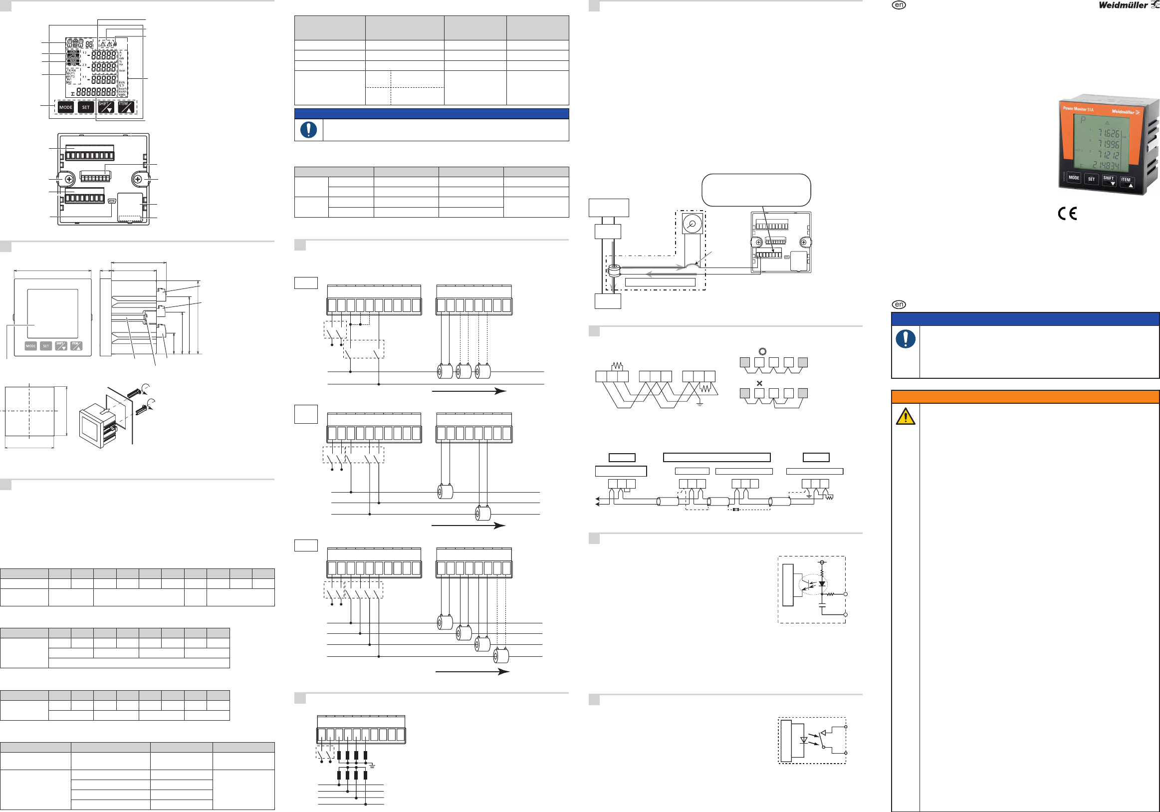
Front view / Rear view
A
Item indication
Sub-indication
Log indication
Keys
Measured value
Unit
Lock mark
Alarm indication
Load ratio indication
TX/RX mark
Pulse output
Pulse input
Terminal block A
Terminal block B
Terminal block C
Battery label
Backup battery
Mounting bracket
Mounting bracket
USB port
Please remove and
throw away the
battery according to
the instruction of your
area when throwing
the product.
Mounting
B
(unit: mm)
(tolerance: ±1.0)
Mounting bracket
Terminal
block A
Terminal
block C
Terminal block B
Mounting screw: M4×10
Display
□ 96
(45.7)
(70.4)
(25.6)
56
(68)
14
□ 91 ±0.4
Panel cut-out Panel mounting
92 ±0.5
92 ±0.5
1) Remove the mounting clips from the
unit.
2) Insert the unit from the front of the
panel.
3) Attach the mounting clips at the both
side of the case and secure in place
with the screws. (Tightening torque:
app. 0.2 to 0.3 Nm)
Applicable panel thickness: 1 to 5 mm
Keep enough space for several mountings. Recommended space: 130mm the left, right, top and bot-
tomfrom center of the unit.
Electrical connections
C
Be sure to wire correctly in accordance with the terminal arrangement and wiring diagrams.
Please connect a fuse or a breaker to the power supply part for safety reasons and to protect the de-
vice.
It does not feature a built-in power switch, circuit breaker or fuse for measured voltage input parts.
They should therefore be installed in the circuit near this unit.
Do not turn on the power supply or input until all wiring is completed.
Never remove the terminal block while applying current to load. It might cause electric shock or CT
breakdown.
Terminal block A
Terminal no. 1 2 3 4 5 6 7 8 9 10
Functions L + N – V1 V2 V3 Vn NC GND D+ D-
AUX
(Power supply)
Measured voltage input
unas-
signed
RS485
Terminal block B
Terminal no. 1 2 3 4 5 6 7 8
Functions
K L K L K L K L
CT1 CT2 CT3 CTn
Measured current input
Terminal block C
Terminal no. 1 2 3 4 5 6 7 8
Functions
OUT1 COM1 OUT2 COM2 IN1+ IN1- IN2+ IN2-
Output 1 Output 2 Input 1 Input 2
Input voltage to each terminal
Terminal Phase and wire system Terminal no. Input voltage
Power supply Single-phase two-wire 1 - 2
85 - 264 V AC
100 - 300 V DC
Measured voltage input
Single-phase two-wire 3 - 6
0 - 500 V AC
Single-phase three-wire 3 - 5 - 6
Three-phase three-wire 3 - 5 - 6
Three-phase four-wire 3 - 4 - 5 - 6
Applicable wire (crimp-type terminal is recommended)
Stripping length: 7 to 8 mm
Power supply /
Measured voltage /
RS485 communication
CT Input
(measured current)
Input / Output
Terminal block A B C
Screw size M2.5 M2.5 M2
Tightening torque 0.4 to 0.5 Nm 0.4 to 0.5 Nm 0.2 to 0.25 Nm
Terminal cross-section
single/stranded wire
1 pc.
0.5 to 4 mm
2
(AWG20 to 12)
0.5 to 4 mm
2
(AWG20 to 12)
0.5 to 1.5 mm
2
(AWG20 to 16)
2 pcs.
0.5 to 2 mm
2
(AWG20...14)
NOTICE
• Use shielded cable for RS485 communication.
• Use applicable cable according to the measured current.
Applicable ferrules (by Weidmüller)
Wire size 0.75 mm
2
1.25 mm
2
2 mm
2
*
1 pc.
Name H0.75/14D GR H1.5/14D SW H2.5/15D BL
Part number 9019040000 9019120000 9019160000
2 pcs. *
Name H0.75/14D ZH GR H1.5/16D ZH SW
–
Part number 9037410000 9037470000
*Only for terminal block A and B. It can not be used for terminal block C.
Wiring diagram
D
• Recommended breaker: 3 to 15 A
• Recommended fuse: Time-lag fuse rated current 2 A
1P2W
Terminal block A (upper) Terminal block B (lower)
Breaker
(To measure
3-circuit)
(To measure 3-circuit)
AUX
(Power supply)
Power
supply side
Load side
CT1 CT2 CT3
L1(R)
N
L+
N-
V1 V2 V3 Vn
NC SG
D+ D-
CT1
k
CT1
l
CT2
k
CT2
l
CT3
k
CT3
l
CTn
k
CTn
l
K
L
1234 6789 12345678510
X
X
XX
1P3W
3P3W
Terminal block A (upper) Terminal block B (lower)
Breaker
AUX
(Power supply)
Power
supply side
L+
N-
V1 V2 V3 Vn
NC SG
D+ D-
CT1
k
CT1
l
CT2
k
CT2
l
CT3
k
CT3
l
CTn
k
CTn
l
1234 6789 12345678510
CT3
L1(R)
L2(N/S)
L3(T)
CT1
Load side
K
L
XXXXX
3P4W
Terminal block A (upper) Terminal block B (lower)
Breaker
AUX
(Power supply)
Power
supply side
L+
N-
V1 V2 V3 Vn
NC SG
D+ D-
CT1
k
CT1
l
CT2
k
CT2
l
CT3
k
CT3
l
CTn
k
CTn
l
1234 6789 12345678510
Connect CTn to measure N-phase.
CTn is not necessary for normal measurement.
CT1
CT2
CT3
L1(R)
L2(S)
L3(T)
N
CTn
(To measure
N-phase)
Load side
K
L
XXXXXX
Voltage Transformer (VT) connection
E
VT (Voltage Transformer)
L1(R)
L2(S)
L3(T)
N
Breaker
AUX
(Power supply)
X X
Terminal block A (upper)
1 2 3 4 5 6 7 8 9 10
Current Transformer (CT) connection
F
• Use a CT with a secondary side current of 5 A or 1 A, the rated burden 0.5 VA or more.
• One CT is needed for one unit when measuring 1P2W (2 CTs for 2 circuits, 3 CTs for 3 circuits). Two
CTs are needed when measuring 1P3W/3P3W. Three CTs are needed when measuring 3P4W.
• Use the appropriate or it might cause a breakdown, burnout or electric shock.
• WhenconnectingtheCT,connectthesecondarysidetotheterminalofthemainunitrst,thenwire
the primary side to a load electric wire. Not keeping to this sequence may cause an electric shock or
CT breakdown.
• The CT has polarity. Wire correctly in accordance with the K and L marks. Wiring in the wrong direc-
tion will result in incorrect measurement.
• If harmonic or waveform distortion occurs, measurements may be inaccurate. Please check the cur-
rent system before adopting it.
• Separate the wiring (strong electric part) of the measured voltage input terminal (operating power
supply terminal) from the CT cable. It may not satisfy the accuracy requirements due to noise.
How to connect the CT
(1) Power off the measured devices.
(2) Install the appropriate CT.
(3) Remove terminal block of Power Monitor 51A.
(4) Connect the CT to the terminal block.
(5) Insert the terminal stand securely.
(6) After ensuring that all the wiring is correct, turn on the power of the load and
Power Monitor 51A.
Power supply
Breaker
Load
Primary side current
Secondary side current
Ammeter etc.
without
Ammeter
(3) (4) (5)
(2)
(1) (6)
K
L
k
l
• Connect CT wiring and terminal block securely,
otherwise it will cause a CT breakdown.
• Never remove the terminal block while applying
current to load. It might cause electric shock
or CT breakdown.
CT (secondary current 1A or 5A)
RS485 connection
G
RS485 communication wiring
Terminal
device
Terminal
device
Correct
Not correct
Terminal block A
(upper)
Class D
120 Ω
1/2 W or more
Upper device
RS485 device
GNDGND
8 9 10
Terminal block A
(upper)
8 9 10
D++
‒
D‒ GND D+ D‒
For terminal stations of both side including the upper device, termination resistors should be connected.
Connect120Ω,½Wormoreterminationresistorbetween[D+]and[D-]ofthePowerMonitor51Athat
is connected to the end of RS485 transmission line.
Connection of Power Monitor 51A and the other devices with 2-wire
Except Power Monitor Power Monitor terminal
class D
120 Ω
1/2 W or more
Terminal device
except Power Monitor
terminal connection
To RS485 device
Shielded cable
Shielded cable
Shielded cable
Short-circuit [–] to [E].
* Do not connect
shielded cable to [E].
* Do not connect
shielded cable to [E].
* Connect
Power Monitor
Terminal TerminalExcept terminals
E+
–
D+GNDD–
D+GNDD–
E+–
Input connection
H
Pulse input
•
R
R
C
IN+
5 or 7
IN–
6 or 8
Photo-
coupler
Internal circuit
Contact input
Use highly reliable metal plated contacts. Since the contact’s
bounce time results directly in an error in the count value, use
contacts with as short a bounce time as possible. In general, se-
lect 30 Hz for max. counting speed.
• Non-contact input (transistor input)
Connect with an open collector. Use the transistor with the fol-
lowingspecications:
V
CEO min
= 20 V / I
C min
= 20 mA / I
CBO max
=6μA
Use transistors with a residual voltage of less than 3 V when the
transistor is ON.
Notes
Short-circuitimpedanceshouldbelessthan1kΩ.
Open-circuitimpedanceshouldbemorethan100kΩ.
The short-circuit leakage current is about 10 mA.
• Input wiring
Please wire as short as possible by using a shielded wire or a metallic electric wire tube individually.
Output connection
I
PhotoMOS relay output
•
OUT
COM
1 or 3
2 or 4
Internal circuit
It adopts PhotoMOS relay output, there is no polarity.
• Please wire less than 100 m for output.
• Output rated capacity: 30 V AC/DC, 0.1 A)
Weidmüller Interface GmbH & Co. KG
Klingenbergstraße 16
D-32758 Detmold
Phone +49 (0) 5231 14-0
Fax +49 (0) 5231 14-292083
info@weidmueller.com
www.weidmueller.com
Safety instructions
NOTICE
• Read these instructions carefully to ensure proper installation.
• After installation, keep them in a safe place for future reference.
• Power Monitor 51A is designed primarily for managing energy-saving. It
is neither intended nor can it be legally used for billing.
• Power Monitor 51A is designed to be installed in a control panel.
WARNING
• PleaseusePowerMonitor51Aaccordingtothespecicationsdescribed.
Otherwise,itmaymalfunctionorcausereandanelectricshock.
◊ Connect Power Monitor 51A to the power supply in compliance with
the rating.
◊ Refer to the wiring diagram to ensure proper wiring for the power
supply, input and output.
◊ Use an electric wire that is appropriate for the rated current.
◊ Do not perform wiring or installation with a live line. This may result in
circuitburnoutorrebywayofthesecondaryCTsideopening.
• Do not connect the voltage input, current input or pulse input wires
parallel to high-voltage or power cables and avoid using the same
conduit. Keep the length of shielded wires as short as possible.
• Do not turn on the power supply or input until all the wiring is completed.
• Do not use the secondary side circuit of inverter. It might cause
exothermic heat or damage.
• If additional noise effects the power supply line, voltage input line or
current input line, incorrect measurements may result.
• Installation and wiring electrical work or electric piping must be
performed by specialist personnel.
• Please wipe dirt off the main unit using a soft cloth etc. Using thinner
might result in deformation or discolouration of the unit.
• Do not add an excess power to the display. It might break the inner liquid
crystal.
• For your safety ensure that the following conditions are met:
◊ Overvoltage category II and pollution degree 2
◊ Indoor use
◊ Ambient temperature of -25 to +55 °C
◊ Ambient non-condensing humidity of 30 to 85% RH (at 20 °C)
◊ Altitude of 2000 m or less
• Do not use in the following environments:
◊ Where it will be exposed to direct sunlight
◊ Whereinammableorcorrosivegasmightbeproduced
◊ Where it will be exposed to excessive airborne dust or metal particles
◊ Where it will be exposed to water, oil or chemicals
◊ Where direct vibration or shock might be transmitted
◊ In the vicinity of high-voltage cables, power lines or machinery where
large switching surges may occur Always use current transformers for
galvanic isolation to measure currents.
• Always use current transformers for galvanic isolation to measure cur-
rents.
1481410000/01/10.16