
User Documentation

- 8 -
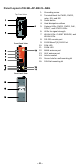
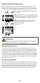
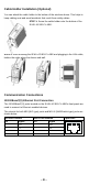
Wiring the Redundant Power Inputs
The top two pairs of contacts of the 10-contact terminal block connector on the
IE-WL-AP-BR-CL-ABG’s top panel are used for the IE-WL-AP-BR-CL-ABG’s two
DC inputs. Top and front views of the terminal block connector are shown below.
STEP 1: Insert the negative/positive DC wires into the
V-/V+ terminals.
STEP 2: To keep the DC wires from pulling loose, use
a small flat-blade screwdriver to tighten the wire-clamp
screws on the front of the terminal block connector.
STEP 3: Insert the plastic terminal block connector
prongs into the terminal block receptor, which is
located on the top panel
of the device.
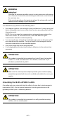
ATTENTION
Before connecting the IE-WL-AP-BR-CL-ABG to the DC power inputs,
make sure the DC power source voltage is stable.
Wiring the Relay Contact
The IE-WL-AP-BR-CL-ABG has one relay output, which consists of the two
contacts of the terminal block on the IE-WL-AP-BR-CL-ABG’s top panel. Refer to
the previous section for detailed instructions on how to connect the wires to the
terminal block connector, and how to attach the terminal block connector to the
terminal block receptor. These relay contacts are used to indicate user-configured
events. The two wires attached to the Relay contacts form an open circuit when a
user-configured event is triggered. If a user-configured event does not occur, the
Relay circuit will be closed.
Wiring the Digital Inputs
The IE-WL-AP-BR-CL-ABG has two sets of digital inputs: DI1 and DI2. Each DI
consists of two contacts of the 10-pin terminal block connector on the top panel of
the device. You can refer to the “Wiring the Redundant Power Inputs” section for
detailed instructions on how to connect the wires to the terminal block connector,
and how to attach the terminal block connector to the terminal block receptor.