
User Documentation

- 6 -
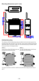
Wall Mounting (optional)
For some applications, it may be more convenient to mount the
IE-WL-AP-BR-CL-ABG to a wall, as illustrated below.
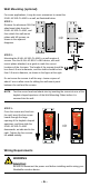
STEP 1:
Remove the aluminum DIN-Rail
attachment plate from the
IE-WL-AP-BR-CL-ABG, and
then attach the wall mount
plates with M3 screws, as
shown in the adjacent
diagrams.
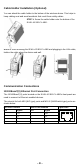
STEP 2:
Mounting the IE-WL-AP-BR-CL-ABG to a wall requires 4
screws. Use the IE-WL-AP-BR-CL-ABG device, with wall
mount plates attached, as a guide to mark the correct
locations of the 4 screws. The heads of the screws should be
less than 6.0 mm in diameter, and the shafts should be less
than 3.5 mm in diameter, as shown in the figure at the right.
Do not screw the screws in all the way—leave a space of
about 2 mm to allow room for sliding the wall mount panel
between the wall and the screws.
NOTE
Test the screw head and shank size by inserting the screw into one of the
keyhole shaped apertures of the Wall Mounting Plates before it is
screwed into the wall.
STEP 3:
Once the screws are fixed into
the wall, insert the four screw
heads through the large
opening of the keyhole-shaped
apertures, and then slide the
IE-WL-AP-BR-CL-ABG
downwards, as indicated to the
right. Tighten the four screws
for added stability.
Wiring Requirements
WARNING
Safety First!
Be sure to disconnect the power cord before installing and/or wiring your
Weidmüller wireless device.