
User Documentation

- 4 -
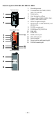
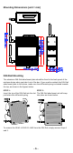
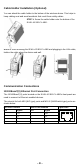
Panel Layout of IE-WL-AP-BR-CL-ABG
1. Grounding screw
2. Terminal block for PWR1, PWR2,
relay, DI1, and DI2
3. Reset button
4. Heat dissipation orifices
5. System LEDs: PWR1, PWR2, PoE,
FAULT, and STATE LEDs
6. LEDs for signal strength
7. WLAN LEDs: CLIENT BRIDGE, and
WLAN LEDs
8. RS-232 console port
9. 10/100BaseT(X) RJ45 Port
10. 10M LED
11. 100M LED
12. MAIN antenna port
13. AUX antenna port
14. Article number
15. Screw hole for wall mounting kit
16. DIN-Rail mounting kit
Front Panel View
Rear Panel View
Top Panel View