
User Documentation


IE-WL-AP-BR-CL-ABG Introduction
1-5
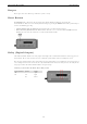
Functional Design
LED Indicators
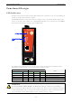
The LEDs on the front panel of the IE-WL-AP-BR-CL-ABG provide a quick and easy means of determining the
current operational status and wireless settings.
The FAULT LED indicates system failures and user-configured events. If the IE-WL-AP-BR-CL-ABG cannot
retrieve the IP address from a DHCP server, the FAULT LED will blink at one second intervals. The SIGNAL
LEDs indicate signal strength, and only operate in Client mode.
The following table summarizes how to read the device’s wireless settings from the LED displays. More
information is available in Chapter 3 in the “Basic Wireless Settings” section.
Basic Wireless Settings LEDs
Operation mode WDS CLIENT BRIDGE SIGNAL
Note
AP Disabled off off – AP mode
AP Enabled off on – Bridge mode: WDS is enabled
Client – on off 0 Client mode: no association
Client – on off 1 Client mode: associated, poor signal
Client – on off 2-5 Client mode: associated, good signal
ATTENTION
The FAULT, SIGNAL, CLIENT, BRIDGE, and WLAN LEDs lighting up simultaneously and blinking at
one-second intervals indicates that the system has failed to boot. This may be due to improper operation or
an uncontrollable factor, such as an unexpected shutdown during firmware update. Instructions on how to
recover the firmware can be found in Chapter 6 in the “Firmware Recovery” section.