
User Documentation


- 11 -
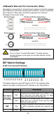
Wiring the Redundant Power Inputs
Both power inputs can be connected simultaneously to live DC power
sources. If one power source fails, the other live source acts as a backup,
and automatically supplies the Ethernet Switch’s power needs.
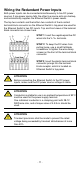
The top two contacts and the bottom two contacts of the 6-contact
terminal block connector on the Ethernet Switch’s top panel are used for
the Ethernet Switch’s two DC inputs. Top and front views of the terminal
block connector are shown here.
STEP 1: Insert the negative/positive DC
wires into the V-/V+ terminals.
STEP 2: To keep the DC wires from
pulling loose, use a small flat-blade
screwdriver to tighten the wire-clamp
screws on the front of the terminal block
connector.
STEP 3
: Insert the plastic terminal block
connector prongs into the terminal
block receptor, which is located on
Ethernet Switch’s top panel.
ATTENTION
Before connecting the Ethernet Switch to the DC power
inputs, make sure the DC power source voltage is stable.
ATTENTION
Conductors suitable for use
in an ambient temperature of 93°C
must be used for the power supply terminal.
One individual conductor in a clamping point with 28-12
AWG wire size, and a torque value of 4.5 lb
-in should be
used.
ATTENTION
Transient provisions shall be made to prevent the rated
voltage being exceeded by transient disturbances of more
than 40%.