
User Documentation


- 9 -
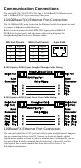
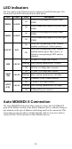
All you need to remember is to connect the Tx (transmit) port of device I to
the Rx (receive) port of device II, and the Rx (receive) port of device I to the
Tx (transmit) port of device II.
SC-Port Pinouts
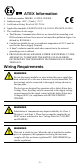
ATTENTION
This is a Class 1 Laser/LED product. To avoid causing serious
damage to your eyes, do not stare directly into the Laser Beam.
Redundant Power Inputs
Both power inputs can be connected simultaneously to live DC power sources.
If one power source fails, the other live source acts as a backup, and
automatically supplies all of IE-SW-VL09-Switch power needs.
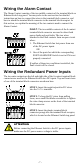
Alarm Contact
The Ethernet Switch has one Alarm Contact located on the top panel. For
detailed instructions on how to connect the Alarm Contact power wires to the
two middle contacts of the 6-contact terminal block connector, see the Wiring
the Alarm Contact section on page 8. A typical scenario would be to connect
the Fault circuit to a warning light located in the control room. The light can be
set up to switch on when a fault is detected.
The Alarm Contact has two terminals that form a Fault circuit for connecting to
an alarm system. The two wires attached to the Fault contacts form an open
circuit when (1) Ethernet Switch has lost power from one of the DC power
inputs, or (2) one of the ports for which the corresponding PORT ALARM DIP
Switch is set to ON is not properly connected.
If neither of these two conditions occurs, the Fault circuit will be closed.
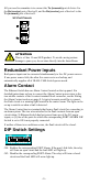
DIP Switch Settings
ON: Enables the corresponding PORT Alarm. If the port’s link fails, the relay
will form an open circuit and the fault LED will light up.
Off: Disables the corresponding PORT Alarm. The relay will form a closed
circuit and the Fault LED will never light up.