
User Documentation
- 7 -
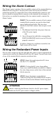
Wiring the Alarm Contact
The Alarm Contact consists of the two middle contacts of the terminal block on
Ethernet Switch top panel. You may refer to the next section for detailed
instructions on how to connect the wires to the terminal block connector, and
how to attach the terminal block connector to the terminal block receptor. In
this section, we explain the meaning of the two contacts used to connect the
Alarm Contact.
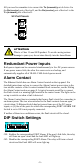
FAULT: The two middle contacts of the 6-contact
terminal block connector are used to detect both
power faults and port faults. The two wires
attached to the Fault contacts form an open circuit
when:
1. The Ethernet Switch has lost power from one
of the DC power inputs.
OR
2. One of the ports for which the corresponding
PORT ALARM DIP Switch is set to ON is not
properly connected.
If neither of these two conditions is satisfied, the
Fault circuit will be closed.
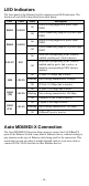
Wiring the Redundant Power Inputs
The two outer contacts on the left and right side of the 6-contact terminal block
connector are used for the Ethernet Switch two DC inputs. Top and front views
of one of the terminal block connectors are shown here.
STEP 1: Insert the negative/positive DC wires
into the V-/V+ terminals.
STEP 2: To keep the DC wires from pulling
loose, use a small flat-blade screwdriver to tighten
the wire-clamp screws on the front of the terminal
block connector.
STEP 3: Insert the plastic terminal block
connector prongs into the terminal block receptor,
which is located on the Ethernet Switch top panel.
ATTENTION
Before connecting the Ethernet Switch to the DC power inputs,
make sure the DC power source voltage is stable.