
User Documentation

- 10 -
LED Indicators
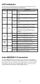
The front panel of the Ethernet Switch contains several LED indicators. The
function of each LED is described in the table below.
LED
Color
State
Description
PWR1
AMBER
On
Power is being supplied to power input
PWR1
Off
Power is not being supplied to power input
PWR1
PWR2
AMBER
On
Power is being supplied to power input
PWR2
Off
Power is not being supplied to power input
PWR2
FAULT
RED
On
When the corresponding PORT alarm is
enabled, and the port’s link is inactive.
Off
When the corresponding PORT alarm is
enabled and the port’s link is active, or
when the corresponding PORT alarm is
disabled.
10M
GREEN
On
TP port’s 10 Mbps link is active
Blinking
Data is being transmitted at 10 Mbps
Off
TP Port’s 10 Mbps link is inactive
100M
(TP)
GREEN
On
TP port’s 100 Mbps link is active
Blinking
Data is being transmitted at 100 Mbps
Off
100BaseTX Port’s link is inactive
100M
(FX)
GREEN
On
FX port’s 100 Mbps is active
Blinking
Data is being transmitted at 100 Mbps
Off
100BaseFX port is inactive
Auto MDI/MDI-X Connection
The Auto MDI/MDI-X function allows users to connect the 10/100BaseTX
ports of the Ethernet Switch to any kind of Ethernet device, without needing to
pay attention to the type of Ethernet cable being used for the connection. This
means that you can use either a straight-through cable or cross-over cable to
connect IE-SW-VL09-Switches to other Ethernet devices.