Ethernet Switch – Value Line IE-SW-VL09T-6TX-3SC (Unmanaged) Hardware Installation Guide Fourth Edition, August 2016 1243510000/03/08.16 Please note: This document and any further product information if available - can be downloaded at the internet link: http://www.weidmueller.com/downloads Copyright Notice Copyright 2016 Weidmüller Interface GmbH & Co. KG All rights reserved. Reproduction without permission is prohibited.
Overview The switch IE-SW-VL09T-6TX-3SC with 6 Copper-and 3 SC-Fiber-Ports provides an economical solution for your Ethernet connections. As an added bonus, the built-in smart alarm function helps system maintainers monitor the health of your Ethernet network. This Ethernet switch has a wide operating temperature range of -40 to 75°C, and is designed to withstand a high degree of vibration and shock.
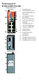
Panel Layout of IE-SW-VL09T-6TX-3SC IE-SW-VL09T-6TX-3SC Front Panel 1. 2. 3. 4. 5. 6. 7. 8. 9. 10. 11. 12. 13. Top Panel View 14. 15. 16. 17.
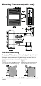
Mounting Dimensions (unit = mm) DIN-Rail Mounting The aluminum DIN-Rail attachment plate should already be fixed to the back panel of the Ethernet Switch when you take it out of the box. If you need to reattach the DIN-Rail attachment plate, make sure the stiff metal spring is situated towards the top, as shown in the figures below. STEP 1: STEP 2: Insert the top of the DIN-Rail into the The DIN-Rail attachment unit will slot just below the stiff metal spring. snap into place as shown below.
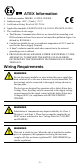
ATEX Information 1. Certificate number DEMKO 11 ATEX 150188X 2. 3. 4. 5. Ambient range: -40°C ≤ Tamb ≤ +75°C Certification String: Ex nA nC IIC T4 Gc Applicable standards: EN 60079-0:2012+A11:2013, EN 60079-15:2010 The conditions of safe usage: a. The Ethernet Communication Devices are intended for mounting in an IP54 enclosure and used in an area of not more than pollution degree 2 as defined by IEC60664-1 b.
WARNING Safety First! Be sure to disconnect the power cord before installing and/or wiring your Ethernet Switch. Calculate the maximum possible current in each power wire and common wire. Observe all electrical codes dictating the maximum current allowable for each wire size. If the current goes above the maximum ratings, the wiring could overheat, causing serious damage to your equipment. You should also pay attention to the following items: Use separate paths to route wiring for power and devices.
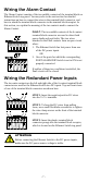
Wiring the Alarm Contact The Alarm Contact consists of the two middle contacts of the terminal block on Ethernet Switch top panel. You may refer to the next section for detailed instructions on how to connect the wires to the terminal block connector, and how to attach the terminal block connector to the terminal block receptor. In this section, we explain the meaning of the two contacts used to connect the Alarm Contact.
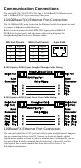
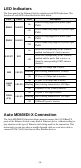
Communication Connections The switch IE-SW-VL09T-6TX-3SC has 6 10/100BaseT(X) Ethernet ports, and 3 100BaseFX (SC-type connector) fiber ports. 10/100BaseT(X) Ethernet Port Connection The 10/100BaseT(X) ports located on the Ethernet Switch front panel are used to connect to Ethernet-enabled devices. Below we show pinouts for both MDI (NIC-type) ports and MDI-X (HUB/Switch-type) ports, and also show cable wiring diagrams for straight-through and cross-over Ethernet cables.
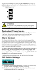
All you need to remember is to connect the Tx (transmit) port of device I to the Rx (receive) port of device II, and the Rx (receive) port of device I to the Tx (transmit) port of device II. SC-Port Pinouts ATTENTION This is a Class 1 Laser/LED product. To avoid causing serious damage to your eyes, do not stare directly into the Laser Beam. Redundant Power Inputs Both power inputs can be connected simultaneously to live DC power sources.
LED Indicators The front panel of the Ethernet Switch contains several LED indicators. The function of each LED is described in the table below. LED Color PWR1 AMBER State On PWR2 FAULT 10M 100M (TP) 100M (FX) Off Power is not being supplied to power input PWR1 On Power is being supplied to power input PWR2 Off Power is not being supplied to power input PWR2 On When the corresponding PORT alarm is enabled, and the port’s link is inactive.
Fiber Ports Fiber switched ports operate at a fixed 100 Mbps speed and full-duplex mode to provide the best performance. The fiber ports are factory-built as a multi-mode SC connector. Consequently, you should use fiber cables that have SC connectors at both ends. When plugging the connector into the port, make sure the slider guide is positioned to the right side so that it fits snuggly into the port.
Auto-Negotiation and Speed Sensing All of the RJ45 Ethernet ports independently support auto-negotiation for speeds in the 10BaseT and 100BaseTX modes, with operation according to the IEEE 802.3u standard. This means that some nodes could be operating at 10 Mbps, while at the same time other nodes are operating at 100 Mbps. Auto-negotiation takes place when an RJ45 cable connection is made, and then each time a LINK is enabled.
Power Input Voltage Input Current @ 24VDC Connection Overload Current Protection Reverse Polarity Protection Mechanical Casing Dimensions Weight Installation Environmental Operating Temperature Storage Temperature Ambient Relative Humidity 12 to 48 VDC, redundant inputs IE-SW-VL09T-6TX-3SC: 0.35 A Removable “6-pin” Terminal Block IE-SW-VL09T-6TX-3SC: 1.6 A Present IP30 protection, metal case 53.6 135 105 mm (W H D) 0.
Weidmüller gives a 5 year warranty on this product in accordance with the warranty terms as described in the general conditions of sale of the Weidmüller company which has sold the products to you. Weidmüller warrants to you that such products the defects of which have already existed at the time when the risk passed will be repaired by Weidmüller free of charge or that Weidmüller will provide a new, functionally equivalent product to replace the defective one.