
User Documentation


User Manual Managed Switches
33
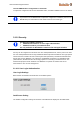
If DIP switch 4 is set to ON then the Webinterface menu ‘Communication Redundancy’ is locked,
showing the selected Turbo Ring version. DIP switch 4 overrules the redundancy settings of the
Webinterface.
The role of the switch (Master yes/no, Coupler yes/no) will be set by DIP switches 2 and 3.
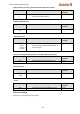
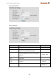
Behavior of DIP Switch settings when protocol is set to ‘Turbo Ring V1’
DIP 1
DIP 2
DIP 3
DIP 4
Reserved for future
use.
ON: Enables this
SWITCH as the Ring
Master.
ON: Enables the
default “Ring
Coupling” ports.
ON: Activates DIP
switches 1, 2, 3 to
configure Turbo
Ring settings.
OFF: This SWITCH
will not be the Ring
Master.
OFF: Do not use this
SWITCH as the ring
coupler.
OFF: DIP switches 1,
2, 3 will be disabled.
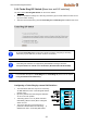
Behavior of DIP Switch settings when protocol is set to ‘Turbo Ring V2’
DIP 1
DIP 2
DIP 3
DIP 4
ON: Enables the
default “Ring
Coupling (backup)”
port.
ON: Enables this
SWITCH as the Ring
Master.
ON: Enables the
default “Ring
Coupling” port.
ON: Activates DIP
switches 1, 2, 3 to
configure Turbo
Ring V2 settings.
OFF: Enables the
default “Ring
Coupling (primary)”
port.
OFF: This SWITCH
will not be the Ring
Master.
OFF: Do not use this
SWITCH as a ring
coupler.
OFF: DIP switches 1,
2, 3 will be disabled.
Regarding the used ports for Ring redundancy and Ring coupling please refer to
section Communication redundancy (Chapter 3.5.3.1 Configuring Turbo Ring V1,
Chapter 3.5.3.2 Configuring Turbo Ring V2 ).
By factory defaults the Turbo Ring DIP Switches are set to the OFF position.
The Turbo Ring Ports and Coupling Ports will be added automatically to all VLANs if
you set DIP Switch 4 to the “ON” position.