
User Documentation


- 4 -
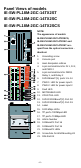
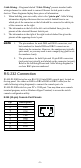
Panel Views of models
IE-SW-PL18M-2GC-14TX2ST
IE-SW-PL18M-2GC-14TX2SC
IE-SW-PL18M-2GC-14TX2SCS
NOTE:
The appearance of models
IE-SW-PL18M-2GC14TX2SCS,
IE-SW-PL18M-2GC14TX2SC and
IE-SW-PL18M-2GC14TX2ST are -
apart from the optical connectors -
identical.
1. Grounding screw
2. Console port
3. Heat dissipation orifices
4. 6-pin terminal block for DI 1, DI 2,
and PWR 2
5. 6-pin terminal block for PWR1
Relay 1, and Relay 2
6. 10/100BaseT(X), ports 1 to 14
7. PWR 1: LED for power input 1
8. PWR 2: LED for power input 2
9. Fault LED
10. MSTR/HEAD LED
11. CPLR/TAIL LED
12. 10/100/1000BaseT(X) Port G2
13. 10/100/1000BaseT(X) Port G1
14. Label
15. 1000 Mbps LEDs
16. TP port’s 100 Mbps LED
17. TP port’s 10 Mbps LED
18. Article Number
19. 100BaseFX Port 16
20. 100BaseFX Port 15
21. 100BaseFX LEDs
22. Screw hole for Wall Mounting Kit
23. DIN-Rail Kit