
User Documentation

- 9 -
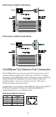
Cable Wiring—Diagrams labeled “Cable Wiring” present standard cable
wiring schemes for cables used to connect Ethernet Switch ports to other
devices. These diagrams display three pieces of information:
1. When building your own cable, refer to the “pin-to-pin” Cable Wiring
information displayed between the two vertical dashed lines to see
which pin of the connector on the left should be connected to which pin
of the connector on the right.
2. The information to the left of the left vertical dashed lines gives the
pinouts of the relevant Ethernet Switch port.
3. The information to the right of the right vertical dashed line gives the
pinouts of the opposing device’s port.
NOTE
1. The pin numbers for male DB9 and DB25 connectors, and
hole numbers for female DB9 and DB25 connectors are
labeled on the connector. However, the numbers are typically
quite small, so you may need to use a magnifying glass to see
the numbers clearly.
2. The pin numbers for both 8-pin and 10-pin RJ45 connectors
(and ports) are typically not labeled on the connector (or port).
Refer to the following Pinout and Cable Wiring diagrams to
see how RJ45 pins are numbered
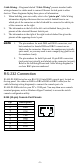
RS-232 Connection
IE-SW-PL18M Series has one RS-232 (10-pin RJ45) console port, located on
the top panel. Use either an RJ45-to-DB9 or RJ45-to-DB25 cable (see the
cable following wiring diagrams) to connect the console port of a
IE-SW-PL18M switch to your PC’s COM port. You may then use a console
terminal program, such as Windows Hyper Terminal, to access the switch
console configuration utility.
RJ45 (10-pin) Console Port Pinouts
Pin
Description
1
------
2
DSR
3
------
4
GND
5
TxD
6
RxD
7
GND
8
------
9
DTR
10
------