
User Documentation

- 7 -
You should also pay attention to the following points:
Use separate paths to route wiring for power and devices. If power wiring
and device wiring paths must cross, make sure the wires are perpendicular
at the intersection point
NOTE: Do not run signal or communications wiring and power wiring
through the same wire conduit. To avoid interference, wires with different
signal characteristics should be routed separately
You can use the type of signal transmitted through a wire to determine
which wires should be kept separate. The rule of thumb is that wiring that
shares similar electrical characteristics can be bundled together
Separate input wiring and output wiring
We advise that you label wiring to all devices in the system when
necessary.
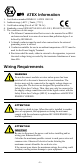
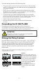
Grounding the IE-SW-PL18M
Grounding and wire routing help limit the effects of noise due to
electromagnetic interference (EMI). Run the ground connection from the
ground screw to the grounding surface prior to connecting devices.
ATTENTION
This product is intended to be mounted to a well-grounded
mounting surface such as a metal panel.
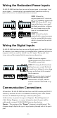
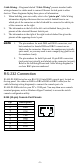
Wiring the Relay Contact
IE-SW-PL18M-Switches have two sets of relay outputs - relay 1 and relay 2.
Each relay contact consists of the two contacts of the terminal block on the
top panel of IE-SW-PL18M-Switch. You can refer to the next section for
detailed instructions on how to connect the wires to the terminal block
connector, and how to attach the terminal block connector to the terminal
block receptor.
In this section, we will explain the meaning of the two contacts used to
connect the Relay Contact.
FAULT:
The two sets of relay contacts of
the 6-pin terminal block connector
are used to detect user-configured
events. The two wires attached to
the fault contacts form an open
circuit when a user-configured
event is triggered. If a
user-configured event does not
occur, the fault circuit remains
closed.