Ethernet Switch – Premium Line IE-SW-PL16M Series (Managed) Hardware Installation Guide Fifth Edition, August 2016 1243370000/04/08.16 Please note: This document, the detailed manual and any further product information - if available - can be downloaded at the internet link: http://www.weidmueller.com/downloads Copyright Notice Copyright 2016 Weidmüller Interface GmbH & Co. KG All rights reserved. Reproduction without permission is prohibited.
Package Checklist Your Ehernet Switch is shipped with the following items. If any of these items are missing or damaged, please contact your Weidmüller customer service for assistance. 1 Ethernet Switch IE-SW-PL16M Hardware Installation Guide CD-ROM with User’s Manual and Windows Utility (option) Please download CD-ROM from Internet page http://www.weidmueller.
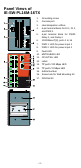
Panel Views of IE-SW-PL16M-16TX 1. 2. 3. 4. 5. 6. 7. 8. 9. 10. 11. 12. 13. 14. 15. 16. 17.
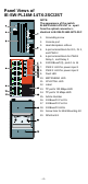
Panel Views of IE-SW-PL16M-14TX-2SC/2ST NOTE: The appearance of the switch IE-SW-PL16M-14TX-2ST is - apart from the optical connectors identical to IE-SW-PL16M-14TX-2SC 1. Grounding screw 2. 3. 4.
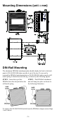
Mounting Dimensions (unit = mm) DIN-Rail Mounting The aluminum DIN-Rail attachment plate should already be fixed to the back panel of IE-SW-PL16M when you take it out of the box. If you need to reattach the DIN-Rail attachment plate to IE-SW-PL16M, make sure the stiff metal spring is situated towards the top, as shown by the following figures. STEP 1—Insert the top of the DIN-Rail into the slot just below the stiff metal spring.
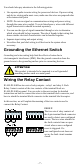
ATEX Information 1. 2. 3. 4. 5. Certification number DEMKO 11 ATEX 150191X Ambient range (-40°C ≤ Tamb ≤ 75°C) Certification string (Ex nA nC IIC T4 Gc) Standards covered (EN 60079-0:2012+A11:2013, EN 60079-15:2010) The conditions of safe usage: The Ethernet Communication Devices are to be mounted in an IP54 enclosure and used in an area of not more than pollution degree 2 as defined by IEC60664-1. A 4mm2 conductor must be used when connection to the external grounding screw is utilized.
You should also pay attention to the following points: Use separate paths to route wiring for power and devices. If power wiring and device wiring paths must cross, make sure the wires are perpendicular at the intersection point NOTE: Do not run signal or communications wiring and power wiring through the same wire conduit.
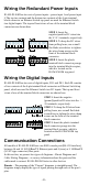
Wiring the Redundant Power Inputs IE-SW-PL16M has two sets of power inputs—power input 1 and power input 2.The top two contacts and the bottom two contacts of the 6-pin terminal block connector on Ethernet Switch top panel are used for Ethernet Switch two digital inputs. The top and front views of one of the terminal block connectors are shown here. STEP 1: Insert the negative/positive DC wires into the V-/V+ terminals, respectively.
Cable Wiring—Diagrams labeled “Cable Wiring” present standard cable wiring schemes for cables used to connect Ethernet Switch’s ports to other devices. These diagrams display three pieces of information: 1. When building your own cable, refer to the “pin-to-pin” Cable Wiring information displayed between the two vertical dashed lines to see which pin of the connector on the left should be connected to which pin of the connector on the right. 2.
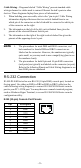
RJ45 (10-pin) to DB9 (F) Cable Wiring Server RJ45 (10-pin) to DB25 (F) Cable Wiring Server 10/100BaseT(X) Ethernet Port Connection The 10/100BaseT(X) ports located on Ethernet Switch’s front panel are used to connect to Ethernet-enabled devices.
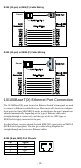
RJ45 (8-pin, MDI-X) Port Pinouts Pin 1 2 3 6 Signal Rx+ RxTx+ Tx- RJ45 (8-pin) to RJ45 (8-pin) Straight-through Cable Wiring RJ45 (8-pin) to RJ45 (8-pin) Cross-over Cable Wiring 100BaseFx Ethernet Port Connection The concept behind the SC/ST port and cable is quite straightforward. Suppose you are connecting devices I and II. As opposed to electrical signals, optical signals do not require a circuit in order to transmit data.
ATTENTION This is a Class 1 Laser/LED product. To prevent damage to your eyes, do not stare directly into the laser beam. LED Indicators The front panel of IE-SW-PL16M contains several LED indicators. The function of each LED is described in the following table: LED Color PWR1 AMBER State On PWR2 FAULT Off Power is not being supplied to power input P1. On Power is being supplied to power input P2. Off Power is not being supplied to power input P2.
Specifications Technology Standards IEEE 802.3 for 10BaseT, IEEE 802.3u for 100BaseT(X) and 100Base FX, IEEE 802.3x for Flow Control, IEEE 802.1D for Spanning Tree Protocol, IEEE 802.1w for Rapid STP, IEEE 802.1Q for VLAN Tagging, IEEE 802.1p for Class of Service, IEEE 802.1X for Authentication, IEEE 802.
Mechanical Casing IP30 protection, metal case Dimensions 95 135 140 mm (W H D) Weight 1.586 kg Installation DIN-Rail, Wall Mounting Environment Operating Temperature 0 to 60°C (32 to 140°F) -40 to 75°C (-40 to 167°F) for -T models Storage Temperature -40 to 85°C (-40 to 185°F) Ambient Relative Humidity 5% to 95% (non-condensing) Regulatory Approvals Safety UL 508, UL60950-1 CSA C22.2 No. 60950-1, EN60950-1 Hazardous Location UL/cUL Class I, Division 2, Groups A, B, C, and D.
Contact Information Weidmüller Interface GmbH & Co. KG Postfach 3030 32760 Detmold Klingenbergstraße 16 32758 Detmold Germany Phone +49 (0) 5231 14-0 Fax +49 (0) 5231 14-2083 E-Mail info@weidmueller.com Internet www.weidmueller.