
User Documentation

- 3 -
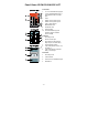
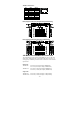
Panel Views IE-SW-PL09M-5GC-4GT
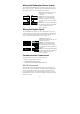
Front Panel:
1. 1 to 4: 10/100/1000 BaseT(X) port
2. 5 to 9: 10/100/1000 BaseT(X) or
100/1000Base SFP slot combo
ports
3. Label
4. PWR1: LED for power input 1
5. PWR2: LED for power input 2
6. FAULT: LED indicator
7. MSTR/HEAD LED
8. CPLR/TAIL LED
9. Article Number
10. 10/100/1000BaseT(X) LED
indicator (Amber: 10/100M
Green: 1000M)
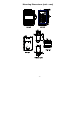
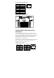
Top Panel:
1. Grounding screw
2. RS-232 console port
3. DIP switches for Ring Master,
Ring Coupler, and Turbo Ring
4. Heat dissipation orifices
5. 6-pin terminal block for DI 1, DI 2,
and PWR 2
6. 6-pin terminal block for PWR1,
Relay 1, and Relay 2
Rear Panel:
1. Grounding screw
2. Terminal block
3. Screw holes for Wall Mounting Kit
4. DIN-Rail kit