Ethernet Switch – Premium Line IE-SW-PL09M-5GC-4GT Hardware Installation Guide Third Edition, October 2012 1243420000/02/10.12 Please note: This document, the detailed manual and any further product information - if available - can be downloaded at the internet link: http://www.weidmueller.com/downloads Copyright Notice Copyright 2012 Weidmüller Interface GmbH & Co. KG All rights reserved. Reproduction without permission is prohibited.
Package Checklist Your Ethernet switch is shipped with the following items. If any of these items is missing or damaged, please contact your Weidmüller customer service for assistance. 1 Ethernet Switch IE-SW-PL09M-5GC-4GT Hardware Installation Guide CD-ROM with User’s Manual and Windows Utility (option) Please download CD-ROM from Internet page http://www.weidmueller.
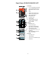
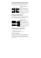
Panel Views IE-SW-PL09M-5GC-4GT Front Panel: 1. 2. 1 to 4: 10/100/1000 BaseT(X) port 5 to 9: 10/100/1000 BaseT(X) or 100/1000Base SFP slot combo ports 3. Label 4. PWR1: LED for power input 1 5. PWR2: LED for power input 2 6. FAULT: LED indicator 7. MSTR/HEAD LED 8. CPLR/TAIL LED 9. Article Number 10. 10/100/1000BaseT(X) LED indicator (Amber: 10/100M Green: 1000M) Top Panel: 1. 2. 3. Grounding screw RS-232 console port DIP switches for Ring Master, Ring Coupler, and Turbo Ring 4.
Mounting Dimensions (unit = mm) -4-
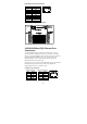
DIN-Rail Mounting The aluminum DIN-Rail attachment plate should already be fixed to the back panel of the IE-SW-PL09M-5GC-4GT when you take it out of the box. If you need to reattach the DIN-Rail attachment plate to the switch, make sure the stiff metal spring is situated towards the top, as shown in the following figures. STEP 1—Insert the top of the DIN-Rail into the slot just below the stiff metal spring. STEP 2—The DIN-Rail attachment unit will snap into place as shown in the following illustration.
Please read and follow these guidelines: Use separate paths to route wiring for power and devices. If power wiring and device wiring paths must cross, make sure the wires are perpendicular at the intersection point. NOTE: Do not run signal or communications wiring and power wiring through the same wire conduit. To avoid interference, wires with different signal characteristics should be routed separately.
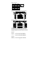
Wiring the Redundant Power Inputs The switch IE-SW-PL09M-5GC-4GT has two sets of power inputs - power input 1 and power input 2 – located on the 6-pin terminal block connector on the top panel of the device. See sketch below how to connect. STEP 1: Insert the negative/positive DC wires into the V-/V+ terminals, respectively. STEP 2: To keep the DC wires from pulling loose, use a small flat-blade screwdriver to tighten the wire-clamp screws on the front of the terminal block connector.
RJ45 (10-pin) Console Port Pinouts Pin 1 2 3 4 5 6 7 8 9 10 Description -----DSR RTS -----TxD RxD GND CTS DTR ------ RJ45 (10-pin) to DB9 (F) Cable Wiring Switch 10/100/1000BaseT(X) Ethernet Port Connection The 10/100/1000BaseT(X) ports located on the front panel are used to connect to Ethernet-enabled devices.
1000BaseT RJ45 Pinouts Pin 1 2 3 4 5 6 7 8 MDI BI_DA+ BI_DABI_DB+ BI_DC+ BI_DCBI_DBBI_DD+ BI_DD- MDI-X BI_DB+ BI_DBBI_DA+ BI_DD+ BI_DDBI_DABI_DC+ BI_DC- RJ45 (8-pin) to RJ45 (8-pin) Straight-Through Cable Wiring RJ45 (8-pin) to RJ45 (8-pin) Cross-Over Cable Wiring 100 BaseFX or 1000BaseSFP Fiber Port The Gigabit Ethernet ports on the IE-SW-PL09M-5GC-4GT are SFP slots, which require 100BaseFX SFP or Gigabit mini-GBIC fiber transceivers to work properly.
Multi mode: 100BaseFX 0 to 5 km, 1300 nm (50/125μm, 800MHz*km) 0 to 4 km, 1300 nm (62.5/125μm, 500MHz*km) Single mode: 100BaseFX 0 to 40 km, 1310 nm (9/125μm, 3.5 PS/(nm*km)) The concept behind the LC port and cable is quite straightforward. Suppose you are connecting devices I and II. Unlike electrical signals, optical signals do not require a circuit in order to transmit data.
IE-SW-PL09M-5GC-4GT DIP Switches The default setting for each DIP Switch is OFF. The following table explains the effect of setting the DIP Switch to the ON position. “Turbo Ring” DIP Switch Settings DIP 1 DIP 2 DIP 3 ON: Enables this ON: Enables the Ethernet Switch default ―Ring as the Ring Coupling‖ ports. Master. Reserved for future use. OFF: This Ethernet Switch will not be the Ring Master. DIP 4 ON: Activates DIP switches 1, 2, 3 to configure ―Turbo Ring‖ settings.
LED Indicators The front panel of the IE-SW-PL09M-5GC-4GT switch contains several LED indicators. The function of each LED is described in the following table: LED Color PWR1 AMBER State On PWR2 FAULT Off Power is not being supplied to power input P1. On Power is being supplied to power input P2. Off Power is not being supplied to power input P2. On When the corresponding PORT alarm is enabled, and a user-configured event is triggered.
Specifications Technology Standards IEEE802.3, 802.3u, 802.3x, 802.1D, 802.1w, 802.1Q, 802.1p, 802.1X, 802.3ad, 802.3z Protocols IGMPv1/v2, GMRP, GVRP, SNMPv1/v2c/v3, DHCP Server/Client, DHCP Option 66/67/82, BootP, TFTP, SNTP, SMTP, RARP, RMON, HTTP, HTTPS, Telnet, SSH, Syslog, Modbus/TCP, SNMP Inform, LLDP, IEEE 1588 PTP, IPv6 MIB MIB-II, Ethernet-like MIB, P-BRIDGE MIB, Q-BRIDGE MIB, Bridge MIB, RSTP MIB, RMON MIB Group 1,2,3,9 Flow Control IEEE802.
Wavelength SFP-M 1300 nm Fast Ethernet SFP-S 1310 nm SFP-L 1550 nm Max. Tx Min. Tx Rx Sensitivity Link Budget Typical Distance -18 dBm -8 dBm -34 dBm 26 dB 4 km a 0 dBm -5 dBm -34 dBm 29 dB 40 km b 0 dBm -5 dBm -34 dBm 29 dB 80 km b 0 dBm -3 dBm -3 dBm Saturation a. 50/125 μm or 62.5/125 μm, 800 MHz * km @ 1300 nm multi-mode fiber optic cable b. 9/125 μm single-mode fiber optic cable Power Input Voltage 12/24/48 VDC, 18 to 30VAC (47 to 63 Hz), redundant inputs Input Current (@24V) 0.
Shock IEC60068-2-27 Free Fall IEC60068-2-32 Vibration IEC60068-2-6 WARRANTY 5 years Weidmüller gives a 5 year warranty on this product in accordance with the warranty terms as described in the general conditions of sale of the Weidmüller company which has sold the products to you.