
User Documentation

3
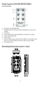
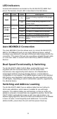
Panel Layout of IE-SW-IP67(T)-5M12
Front Panel View
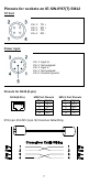
1. M12 port’s 10/100 Mbps LED.
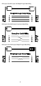
2. 10/100BaseT(X) port (4-pin female shielded M12 socket with D
coding).
3. Port Label.
4. Power input (5-pin male shielded M12 socket with A coding).
5. Power input (PWR) LED.
6. Device Type.
7. Holes for attaching the IE-SW-IP67(T)-5M12 to a wall with screws
(there are 3 holes: bottom left, bottom right, and top middle).
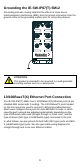
8. Grounding screws.
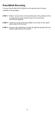
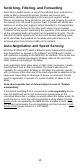
Mounting Dimensions (unit = mm)
Ethernet Switch