
User Documentation


- 9 -
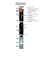
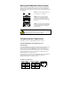
Alarm Contact
The Ethernet Switch has one Alarm Contact located on the top panel. For
detailed instructions on how to connect the Alarm Contact power wires to the
two middle contacts of the 6-contact terminal block connector, see the Wiring
the Alarm Contact section on page 6. A typical scenario would be to connect
the Fault circuit to a warning light located in the control room. The light can be
set up to switch on when a fault is detected.
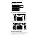
The Alarm Contact has two terminals that form a Fault circuit for connecting to
an alarm system. The two wires attached to the Fault contacts form an open
circuit when (1) Ethernet Switch has lost power from one of the DC power
inputs, or (2) one of the ports, for which the corresponding PORT ALARM
DIP switch is set to ON, is not properly connected.
If neither of these two conditions occurs, the Fault circuit will be closed.
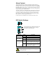
DIP Switch Settings
The default setting for each DIP switch is OFF. The
following table explains the effect of setting the
DIP switches to the ON positions.
DIP Switch
Setting
Description
BSP
ON
Enables broadcast storm protection
OFF
Disables broadcast storm protection
----
refers to Jumbo
Frame
ON
Enables jumbo frame function
OFF
Disables jumbo frame function
PORT Alarm
ON
Enables the corresponding PORT Alarm. If
the port’s link fails, the relay will form an
open circuit and the fault LED will light up.
OFF
Disables the corresponding PORT Alarm.
The relay will form a closed circuit and the
Fault LED will never light up.
ATTENTION
To actively update DIP switch settings, power off and then power
on the Ethernet Switch.