
User Documentation


- 7 -
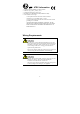
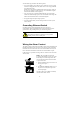
Wiring the Redundant Power Inputs
The top two contacts and the bottom two contacts of the 6-contact terminal
block connector on the Ethernet Switch top panel are used for the Ethernet
Switch DC inputs. Top and front views of one of the terminal block connectors
are shown here.
STEP 1: Insert the negative/positive DC
wires into the V-/V+ terminals.
STEP 2: To keep the DC wires from
pulling loose, use a small flat-blade
screwdriver to tighten the wire-clamp
screws on the front of the terminal block
connector.
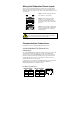
STEP 3: Insert the plastic terminal block
connector prongs into the terminal block
receptor, which is located on Ethernet
Switch top panel.
ATTENTION
Before connecting the Ethernet Switch to the DC power inputs,
make sure the DC power source voltage is stable.
Communication Connections
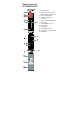
IE-SW-BL05-5GT has 5 10/100/1000BaseT(X) Ethernet ports
10/100/1000BaseT(X) Ethernet Port
Connection
The 10/100/1000BaseT(X) ports located on Ethernet Switch’s front panel are
used to connect to Ethernet-enabled devices. Most users will choose to
configure these ports for Auto MDI/MDI-X mode, in which case the port’s
pinouts are adjusted automatically depending on the type of Ethernet cable
used (straight-through or cross-over), and the type of device (NIC-type or
HUB/Switch-type) connected to the port.
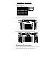
In what follows, we give pinouts for both MDI (NIC-type) ports and MDI-X
(HUB/Switch-type) ports. We also give cable wiring diagrams for
straight-through and cross-over Ethernet cables.
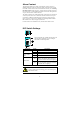
10 /100Base T(x) RJ45 Pinouts
MDI Port Pinouts
MDI-X Port Pinouts
8-pin RJ45
Pin
Signal
Pin
Signal
1
Tx+
1
Rx+
2
Tx-
2
Rx-
3
Rx+
3
Tx+