
User Documentation


- 10 -
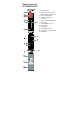
LED Indicators
The front panel of the Ethernet Switch contains several LED indicators. The
function of each LED is described in the table below.
LED
Color
State
Description
PWR1
AMBER
On
Power is being supplied to power input
PWR1
Off
Power is not being supplied to power input
PWR1
PWR2
AMBER
On
Power is being supplied to power input
PWR2
Off
Power is not being supplied to power input
PWR2
FAULT
RED
On
When the corresponding PORT alarm is
enabled, and the port’s link is inactive.
Off
When the corresponding PORT alarm is
enabled and the port’s link is active, or
when the corresponding PORT alarm is
disabled.
10/100/
1000M
AMBER
On
TP port’s 10/100 Mbps link is active
Blinking
Data is being transmitted at 10/100 Mbps
Off
TP Port’s 10/100 Mbps link is inactive
GREEN
On
TP port’s 1000 Mbps link is active
Blinking
Data is being transmitted at 1000 Mbps
Off
TP Port’s 1000 Mbps link is inactive
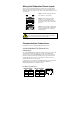
Auto MDI/MDI-X Connection
The Auto MDI/MDI-X function allows users to connect the Ethernet Switch
10/100/1000BaseT(X) ports to any kind of Ethernet device, without paying
attention to the type of Ethernet cable being used for the connection. This
means that you can use either a straight-through cable or cross-over cable to
connect the Ethernet Switch to Ethernet devices.
Triple Speed Functionality and
Switching
The Ethernet Switch 10/100/1000 Mbps RJ45 switched port auto negotiates
with the connected device for the fastest data transmission rate supported by
both devices. The Ethernet Switch is a plug-and-play device, so software
configuration is not required at installation or during maintenance.
The half/full duplex mode for the RJ45 switched ports is user dependent and
changes (by auto-negotiation) to full or half duplex, depending on which
transmission speed is supported by the attached device.