
User Documentation

- 12 -
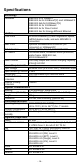
DIP Switch
Setting
Description
BSP
ON
Enables broadcast storm protection
OFF
Disables broadcast storm protection
Jumbo Frame
ON
Enables jumbo frame function
OFF
Disables jumbo frame function
802.3az
ON
Enables the energy-efficient Ethernet
function
OFF
Disables the energy-efficient Ethernet
function
100/1000BaseSFP
ON
Supports 100M SFP module
OFF
Supports 1000M SFP module
Port Alarm
ON
Enables the corresponding PORT
Alarm. If the port’s link fails, the relay
will form an open circuit and the fault
LED will light up
OFF
Disables the corresponding PORT
Alarm. If the port’s link fails, the relay
will form a closed circuit and the fault
LED will never light up
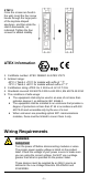
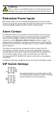
ATTENTION
To actively update DIP switch settings, power off and then
power on the switch.
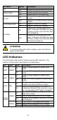
LED Indicators
The front panel of the switch contains several LED indicators. The
function of each LED is described in the table below.
LED
Color
State
Description
PWR1
AMBER
On
Power is being supplied to power input
PWR1
Off
Power is not being supplied to power input
PWR1
PWR2
AMBER
On
Power is being supplied to power input
PWR2
Off
Power is not being supplied to power input
PWR2
FAULT
RED
On
When the corresponding PORT alarm is
enabled, and the port’s link is inactive.
Off
When the corresponding PORT alarm is
enabled and the port’s link is active, or when
the corresponding PORT alarm is disabled.
10/100/
1000M
AMBER
On
TP port’s 10/100 Mbps or SFP port’s 100
Mbps link is active.
Blinking
Data is being transmitted at 10/100 Mbps
Off
TP port’s 10/100 Mbps or SFP port 100 Mbps
link is inactive.
GREEN
On
TP/SFP port’s 1000 Mbps link is active.
Blinking
Data is being transmitted at 1000 Mbps
Off
TP/SFP port’s 1000 Mbps link is inactive