
User Documentation

Hardware Installation Guide for Industrial Security Router (IE-SR-4TX-series)
Version 2.00 / Stand 12.05.2020
PIN Description
GND Reference Potential
D- Inverted data signal
D+ Non-inverted data signal
The fieldbus node is galvanically isolated from power supply. Its
unit load is 1/8.
RJ45 Ethernet connecting
Basically, the configuration of the device is to be done by a
connected PC via web browser. The initial configuration can be
conducted via both the LAN and the WAN interface of the
Router. For the connection both, a standard or a crossover
Ethernet cable can be used. By default, each Ethernet interface
is set to autocrossing / autonegotiation.
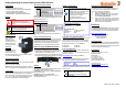
Devices with cellular modems
For Router models with integrated mobile interface the
antenna(s) and the SIM card should be used as follows:
Connect the included or external antenna to the connectors on
top of the housing (1). Insert the SIM card into the SIM slot (2) at
the rear side of the device.
Package Checklist
1 x Weidmüller Industrial Security Router
1 x 4-pin connectors for power supply and digital input
1 x 3-pin connector for RS485 interface
1 x Hardware Installation Guide
1 x Antenna – only for models with cellular modem
Mounting
Warning:
Any installation works on the device are only
permitted if the power supply is switched off,
and if handling the device is safe.
Note:
Please observe applicable security measures
when handling electronic components
sensitive to electrostatic charges
DIN EN61340-5-1 / DIN EN 61340-5-2
DIN-rail mounting
Insert the bottom of the
DIN-rail clip behind the
lower edge of the DIN-rail.
Then open the latch at top
of the device by using a flat-
bladed screwdriver (1) and
fix the device on the DIN-
rail by gently tilting the top
towards the DIN-rail (2).
DIN-rail de-mounting
To remove the Router from
the DIN-Rail, simply reverse the steps described above.
Electrical connecting
Power supply connection
The device must be powered by power supply at 24V DC. The
corresponding 4-pin connector is included in the scope of delivery.
Caution: Risk of electric shock – disconnect the electric power
before servicing.
Attention: risque de choc électrique – débrancher avant la
maintenance.
UL 508 specific terms:
Use only R/C (JDYX2/8.E10480) Fuse Cat. No. 0454003.
manufactured by Littelfuse Inc. or equivalent close to the fuse.
Wire size marking: Use AWG Wire Size 16-24 or equivalent.
Surrounding air temperature rating of 55°C. For use in pollution
degree 2 or equivalent.
Power supply interface:
PIN Description
DI Digital Input
FE
Functional Earth
0V Reference Potential
V+ 24 V DC
Once the power supply is connected to the device, the
PWR LED starts flashing green. If the PWR LED is lit the router is
ready to run.
RS-485 (EIA-485) interface
SIM/Smart-Card
Only SIM- and Smart cards in format ID-000 according to ISO
7816 (25x15 mm) can be used.
The SIM-card for cellular connectivity has to be placed in the top
slot (SIM1)
The Smart card (128 kB) is dedicated for backup of configuration
files and has to be placed in bottom slot (SIM2)
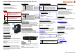
Configuration via Web browser
With factory settings generally, the device can
be configured on both Ethernet interfaces (LAN
and WAN) if the IP address of the connected
port is known. Please note that the IP address
of the configuration PC has to be in the same
IP address r
ange as the connected router port.
Factory default settings:
Language Web interface: English
Operating mode: IP router
Default IP addresses
LAN port: 192.168.1.110 (static value)
Subnet mask: 255.255.255.0
WAN port: DHCP
Configuration of PC network interface
Configure the PC’s network IP address and subnet mask
according to the IP address range of the connected router port.
Example for connection PC Router-LAN-Port:
IP address PC: 192.168.1.99
Subnet mask: 255.255.255.0
Connecting to the Web interface
Start your web browser and enter the IP address of the
connected router port into the browser’s address line.
http://192.168.1.110 (if connected to a LAN port)
After the appearance of prompt (login), please enter the following
login values (factory settings):
User name: admin
Password: Detmold
Confirm your input with "OK". Then the home page of the router
will be displayed.
Note:
If you are using a Proxy server, you must
configure a proxy in the router or deactivate the
proxy
if necessar
y
.
Reset to factory defaults
By pressing the push button "Factory Default" the device can be
reset at any time and regardless of the configuration to the
default factory settings.
How to reset to factory settings:
1. Power off the router
2. Press button „Factory Default“ and keep it hold down
3. Power on the router and keeping pressed button
„Factory Default“ while router is booting
4. Release button „Factory Default“ when PWR LED
starts flashing fast (around 12 seconds after power on)
5. Wait until the PWR LED is glowing constantly green (the
router is ready to run with default settings
General information
The detailed user manual, CE-declaration, additional product
information, tools and any firmware updates can be downloaded
using following link:
https://catalog.weidmueller.com
Select “Active Industrial Ethernet”
Select Industrial Security Router
Select Product model
Click and expand section „Downloads“
Important recommendation:
We strongly recommend that you download the tool Weidmüller
Router-Search-Utility which is very useful to detect Weidmüller
Routers with unknown/forgotten IP addresses (to get access to
the web interface).
Contact information
Weidmüller Interface GmbH & Co. KG
Klingenbergstrasse 26
32758 Detmold
Germany
Phone +49 (0) 5231 14-0
Fax +49 (0) 5231 14-2083
E-Mail info@weidmueller.com
Internet www.weidmueller.com
Technical support:
support.automation@weidmueller.com
1
2
2
1