
User Documentation


Version 1.2 / August 2020 Page 7 / 102
1.4 Mounting the device
Caution
- This device is designed only for an operating voltage range from 19,2 to 28,8 V
DC. Do not use a higher voltage; this could destroy the Router and other devices.
- Connecting plugs should never be connected or disconnected from electrical de-
vices if they are carrying a live load. Be sure to first disconnect all poles of the
plug. Remember to disconnect all plugs from the Router before it is installed or re-
moved.
- Electrical devices should not be installed or removed during operations. Never in-
stall or remove the Router while it is running.
Caution
- It is important to provide sufficient clearance between devices which cause strong
electromagnetic interference (such as frequency converters, transformers or motor
regulators). The clearance gap between such devices and the Router should be as
wide as possible. The Router can be further shielded by using a mu-metal partition.
- The Router is designed to be mounted on a top-hat rail that is compliant with the
EN 50022 standard. This Router will not have a secure mount if any other type of
rail is used. Use a top-hat rail that complies with the EN 50022 standard. Be sure to
observe the mounting information provided by the manufacturer.
Note
- A minimum of 2-inch (5 cm) gap should be kept between the Router and neighbor-
ing devices from the top and bottom. This will ensure that the Router is sufficiently
ventilated.
- The top-hat rail should be in a horizontal position along the vertical rear wall of the
electrical cabinet. This ensures that the Router can be adequately ventilated from
below to above.
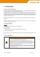
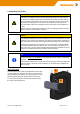
DIN-rail mounting:
Insert the bottom of the DIN-rail clip behind the lower edge
of the DIN-rail. Then open the latch at top of the device by
using a flatbladed screwdriver (1) and fix the device on the
DIN-rail by gently tilting the top towards the DIN-rail (2).
To remove the Router from the DIN-Rail, simply reverse
the steps as described above.
1
2