
User Documentation


Version 1.2 / August 2020 Page 15 / 102
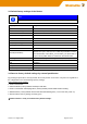
2.3 Pin assignments
Pin assignment of 4-pin connector for „24 V DC power supply and digital input “
Pin number
Description
DI
Digital Input
FE
Functional Earth
0V
GND
V+
24 V DC ± 20 %
Pin assignment of RS485 interface
Pin assignment of RJ45 Ethernet ports (LAN and WAN)
Pin number
SIGNAL NAME (MDI)
10/100Base T(x) 1000Base T
1
TX + BI_DA+
2
TX - BI_DA-
3
RX + BI_DB+
4
NC BI_DC+
5
NC BI_DC-
6
RX - BI_DB-
7
NC BI_DD+-
8
NC BI_DD-
Pin assignment of Smartcard Reader (ISO 7816 Standard)
The integrated SIM card reader is intended for saving and restoring the configuration data.
Pin number
Description
GND
Reference potential
D-
Inverted data signal
D+
Non-inverted data signal
Pin number
SIGNAL NAME
1
VCC 5 Volt
2
RESET
3
CLOCK
4
n/c
5
GND
6
n/c
7
I/O
8
n/c