
User Documentation

Copyright by Weidmüller Interface 18.12.2007, Seite / page 3 von 5 Technische Änderungen vorbehalten/ Technical changes reserved
Weidmüller Interface GmbH & Co KG
.
Klingenbergstr.16
.
D-32758 Detmold Tel.: +49-(0)5231-14-0 Fax: +49-(0)5231-14-2083
D 2.0 Stecker montieren
Abgesetzte Glasfaser und ca. 5mm Sekundärcoating vollständig
mit Aktivator benetzen; dazu aus der Aktivatorspritze eine solche
Menge Aktivator dosieren, dass dieser als Tropfen an der Kanüle
haften bleibt. Faser durch diesen Tropfen „ziehen“ und in den
Stecker einführen, bis diese aus der Bohrung austritt.
Anschließend die Faser 2-3 mal kurz im Stecker hin und her
schieben und am Anschlag verharren lassen. Dabei muss der
Klebstoff auf der Stirnfläche die Faser einhüllen.
Es darf
kein Klebstoff aus dem inneren Metallröhrchen austreten!
Stecker ablegen (Verweilzeit min. 30sec).
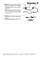
Bei Kabelmontage darauf achten, dass das gesamte
Kevlargeflecht gleichmäßig auf dem Steckerkörper verteilt wird.
(s. Abb.2.0.) Crimphülse bis zum Anschlag aufschieben und mit
Crimpzange SW 4,52 fixieren. Anschließend zum Fixieren des
Kabelmantels mit SW 3,65 auf dem abgesetzten Ende der
Crimphülse crimpen. Überstehendes Kevlargeflecht mit
Kevlarschere abschneiden.
Knickschutztülle über die Crimphülse bis zum Steckerkörper
vorschieben (s. Abb. 2.1).
Überschüssigen nicht ausgehärteten Kleber an der Faser mittels
Reinigungstuch (KIM WIPES) entfernen. Dabei sind die Kanten
des Tuches zu verwenden
.
Wichtig: Vorsichtig arbeiten, damit die überstehende Faser nicht
abgebrochen wird!
Bei korrekter Verarbeitung ist nunmehr ein fester grüner
Klebstoffhügel sichtbar, der die Faser umschließen sollte.
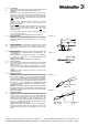
Abb./Fig. 2.0
Crimp SW 4,52
Crimp hex 4,52
Crimp SW 3,65
Crimp hex 3,65
Abb./Fig. 2.1
G
B
2.0
Assembly of plug
A
pply primer on the stripped fibre as well as on the secondary
coating over a length of app. 5 mm by allowing a drop to form on
the tip of the primer bottle nozzle. Move the fibre through this drop
and insert into the connector until the fiber appears on the ferrule
end face. Move the fibre back and forth 2 – 3 times in the
connector, and stop when in the most forward position. The
adhesive on the ferrule end face must now surround the fibre
No adhesive may appear at the end of the most inner metal tube.
Put the plug down (curing time 30 sec. min.).
When assembling the cable, take care that the complete Kevlar
strain relief members cover the connector body uniformly
(s. fig. 2.0). Slide the crimp sleeve on as far as possible and crimp
using the Crimp tool with 4.52 hex size. Then crimp with 3.65 hex
size on the smaller diameter of the crimp sleeve to retain the
jacket. Cut the remaining Kevlar members with Kevlar Cutter.
Push the strain relief sleeve over the connector (s. fig. 2.1).
Remove any surplus adhesive which has not set using a Kim Wipe
tissue; preferable by using the edge of it.
Important: Work carefully in order to prevent the protruding fibre
from breaking.
If the assembly process has been done properly, a solid green
pearl of adhesive should be visible around the fibre.
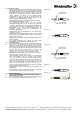
Abb./Fig. 2.0
Crimp SW 4,52
Crimp hex 4,52
Crimp SW 3,65
Crimp hex 3,65
Abb./Fig. 2.1
D
G
B
3.0
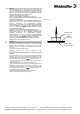
Endfläche bearbeiten
Faser mit Saphir Ritzstift anritzen und abbrechen (s. Abb. 3.0).
Fibre end face preparation
Cleave the fibre with Cleaving tool and break (s. fig. 3.0).
Abb./Fig. 3.0