
User Documentation

- 7 -
Keep input wiring and output wiring separated.
It is strongly advised that you label wiring to all devices in the system
when necessary.
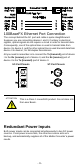
Grounding the Media Converter
Grounding and wire routing help limit the effects of noise due to
electromagnetic interference (EMI). Run the ground connection from the
ground screw to the grounding surface prior to connecting devices.
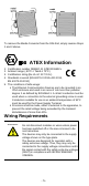
ATTENTION
This product is intended to be mounted to a
well-grounded mounting surface such as a metal
panel.
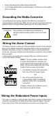
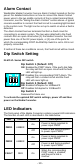
Wiring the Alarm Contact
The Alarm Contact is made up of the two middle contacts of the terminal
block on the Media Converter’s top panel. Refer to the next section for
detailed instructions on how to connect the wires to the terminal block
connector, and how to attach the terminal block connector to the terminal
block receptor.
In this section, we explain the meaning of the two contacts used to
connect the Alarm Contact.
FAULT: The two middle contacts of the
6-contact terminal block connector are
used to detect both power faults and port
faults. The two wires attached to the Fault
contacts form an open circuit when:
1. The Media Converter has lost power
from one of the DC power inputs.
OR
2. One of the ports for which the
corresponding PORT ALARM Dip
Switch is set to ON is not properly
connected.
If neither of these two conditions occurs,
the Fault circuit will be closed.
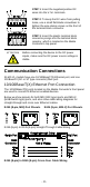
Wiring the Redundant Power Inputs
The outer 2 contacts on left and right side of the 6-contact terminal block
connector are used for the Media Converter’s two DC inputs. Top and
front views of one of the terminal block connectors are shown here.
The