
User Documentation

- 3 -
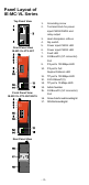
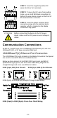
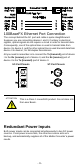
Panel Layout of
IE-MC-VL Series
1. Grounding screw
2. Terminal block for power
input PWR1/PWR2 and
relay output
3. Heat dissipation orifices
4. Dip switch
5. Power input PWR1 LED
6. Power input PWR2 LED
7. Fault LED
8. 100BaseFX (ST connector)
Port
9. FX port’s 100 Mbps LED
10. FX port’s Full
Duplex/Collision LED
11. TP port’s 100 Mbps LED
12. 10/100BaseT(X)
13. TP port’s 10 Mbps LED
14. Article Number
15. 100BaseFX (SC connector)
Port
16. Screw hole for wall mounting kit
17. DIN-Rail mounting kit
Front Panel View
IE-MC-VL-1TX-1ST
Front Panel View
IE-MC-VL-1TX-1SC/1SCS
Top Panel View
Rear Panel View