
User Documentation

- 10 -
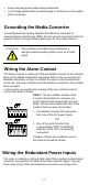
Alarm Contact
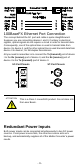
Weidmüller Media Converter has one Alarm Contact located on the top
panel. For detailed instructions on how to connect the Alarm Contact
power wires to the two middle contacts of the 6-contact terminal block
connector, see the “Wiring the Alarm Contact” section above. A typical
scenario would be to connect the Fault circuit to a warning light located
in the control room. The light can be set up to switch on when a fault is
detected.
The Alarm Contact has two terminals that form a Fault circuit for
connecting to an alarm system. The two wires attached to the Fault
contacts form an open circuit when (1) the Media Converter has lost
power from one of the DC power inputs, or (2) one of the ports for
which the corresponding PORT ALARM Dip Switch is set to ON is not
properly connected.
If neither of these two conditions occurs, the Fault circuit will be closed.
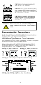
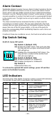
Dip Switch Setting
IE-MC-VL Series DIP switch
Dip Switch 1 (Default: Off )
ON: Enables the PORT Alarm. If the port’s link fails,
the relay will form an open circuit and the fault
LED will light up.
Off: Disables the corresponding PORT Alarm. The
relay will form a closed circuit and the Fault
LED will never light up.
Dip Switch 2 (Default: ON )
ON: Enables full duplex for 100BaseFX
Off: Disables full duplex for 100BaseFX
Dip Switch 3
Reserved for future use
To activate the updated DIP switch settings, power off and then
power on the Media Converter.
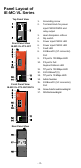
LED Indicators
The front panel of the Media Converter contains several LED indicators.
The function of each LED is described in the table below.
LED
Color
State
Description
PWR1
AMBER
On
Power is being supplied to
power input PWR1
Off
Power is not being supplied
to power input PWR1
PWR2
AMBER
On
Power is being supplied to
power input PWR2
Off
Power is not being supplied
to power input PWR2
FAULT
RED
On
When the corresponding
PORT alarm is enabled,
and the port’s link is
inactive.