Modbus TCP / RTU Gateway Manual for models IE-GW-MB-2TX-1RS232/485 IE-GWT-MB-2TX-1RS232/485 First Edition, May 2014 1536320000/00/05.
Modbus TCP / RTU Gateway Manual IE-GW-MB-2TX-1RS232/485 IE-GWT-MB-2TX-1RS232/485 The software described in this manual is furnished under a license agreement and may be used only in accordance with the terms of that agreement. Copyright Notice Copyright 2014 Weidmüller Interface GmbH &Co. KG. All rights reserved. Reproduction without permission is prohibited. Disclaimer Information in this document is subject to change without notice and does not represent a commitment on the part of Weidmüller.
Contact Information Weidmüller Interface GmbH & Co. KG Postbox 3030 32760 Detmold Klingenbergstraße 16 32758 Detmold Germany Phone: +49(0) 5231 14-0 Fax:+49(0) 5231 14-2083 E-Mail info@weidmueller.com Internet www.weidmueller.
Contents 1. INTRODUCTION .................................................................................................... 5 1.1 Overview Modbus TCP/RTU Gateway ........................................................................................... 5 1.2 Modbus Basics ................................................................................................................................ 6 2. PACKAGE CHECKLIST ...................................................................................
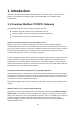
1. Introduction Welcome to the Weidmüller Modbus TCP/RTU gateways. All models feature easy integration of Modbus TCP to Modbus RTU/ASCII and feature RS-232/422/485 ports for Modbus serial communication. 1.
1.2 Modbus Basics Introduction Modbus is one of the most popular automation protocols in the world. It supports both serial and Ethernet devices. Many industrial devices, such as PLCs, DCSs, HMIs, instruments, meters, motors, and drivers use Modbus as their communication standard. Devices are either Masters or Slaves All Modbus devices are classified as either a master or a slave. Masters initiate all communication with slaves and do not communicate to other masters.
Exception The master sends a request to the slave. The slave may not support the command or an error is detected. As result the slave sends an exception to the master. Broadcast The master sends a broadcast command, such as a reset command. Every slave on the network accepts the command. No response is sent to the master.
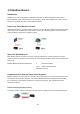
2. Package Checklist All models of Weidmüller Modbus TCP/RTU Gateways are shipped with the following items: 1 Modbus Gateway Hardware Installation Guide (includes Download-Links for this user manual and firmware updates) 3.
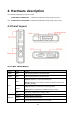
4. Hardware description The hardware information is valid for models IE-GW-MB-2TX-1RS232/485 and Standard Temperature range model (0 to 55°C) IE-GWT-MB-2TX-1RS232/485 Extended Temperature range model (-40 to 75°C) 4.1 Panel Layout 4.2 LED Indicators Name Color Function PWR1 Red Power is being supplied to the power input. PWR2 Red Power is being supplied to the power input. Steady on: Power is on and unit is booting up. Red RDY Steady on: Power is on and unit is running properly.
P1 Orange Serial port is receiving data. Green Serial port is transmitting data. Off No data is being transmitted or received through the serial port. 4.
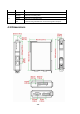
4.4 Jumpers The DIP switches are located beneath the DIP switch panel on the side of the unit. To add a 120 Ω termination resistor set switch 3 to ON. To disable the 120 Ω termination resistor set switch 3 to OFF (default setting). To set the pull high/low resistors to 150 KΩ set DIP switches 1 and 2 to OFF (default setting). To set the pull high/low resistors to 1 KΩ set DIP switches 1 and 2 to ON. Note: DIP switch 4 is not used (reserved for future function).
4.5 DIN-Rail, Wall Mounting There are two sliders on the rear side of the unit for DIN-rail and wall mounting. Mounting on a DIN-rail Pull out the bottom slider, latch the unit onto the DIN-rail, and push the slider back in. Mounting on the wall Pull out both the top and bottom sliders and align the screws accordingly.
4.6 Pin Assignments 4.6.1 DB9 male connector (RS232) Use DB9 connector (male) for RS-232 connections to Modbus RTU or ASCII devices. Pin 1 2 3 4 5 6 7 8 RS-232 DCD RxD TxD DTR GND DSR RTS CTS 4.6.2 Terminal Block (RS-422, RS-485) Use terminal block connector for RS-422 and RS-485 connections to Modbus RTU or ASCII devices. Pin RS-422 RS-485 (4-wire) RS-485 (2-wire) 1 2 3 4 5 TxD+ TxDRxD+ RxDGND ----Data+ DataGND 4.6.
5. Specifications Software Features Operation Modes RTU Slave, RTU Master, ASCII Slave, ASCII Master Multi-Masters and Multi-Request 16 simultaneous TCP masters, 32 simultaneous requests for each TCP master Serial redirection, Priority control Power Requirements Power Input 12 to 48 VDC Max. 435 mA @ 12 VDC, Power Consumption Max. 130 mA @ 48 VDC Physical Characteristics Housing Plastic, IP30 Dimensions 29 (W) x 124.5 (H) x 89.
Flow Control RTS/CTS, XON/XOFF Alarm Contact 1 relay output with a current capacity of 1 A @ 30 VDC Conditions: Relay Output Open when Power-off or when a relay-based alarm is triggered Closed when Power-on and no relay-based alarm is triggered Environmental Limits 0 to 55°C (32 to 131°F), Operating Temperature -40 to 75°C (-40 to 167°F) for –T model Storage Temperature -40 to 85 °C (-40 to 185 °F) Operating Humidity 5 to 95% RH Regulary Approvals FCC Part 15 Subpart B Class A EN 55022 Class A EN
6. Getting Started 6.1 Reset to factory default values by external Reset button The reset button – located on top side of the housing - is used to load factory defaults. Use a pointed object such as a straightened paper clip to hold the reset button down for 5 seconds. Release the reset button when the Ready LED stops blinking. 6.2 Connecting Power Connect the unit to a power source of range 12 to 48 VDC. For pin assignments of power terminal block please refer to chapter 4.6 (Pin Assignments).
7. Device Configuration The Modbus TCP/RTU Gateway can be configured via one of the 2 Ethernet ports by Integrated Webinterface Telnet Console or by PC-based utility “Modbus Gateway Administrator” 7.1 Device configuration by Web-Interface The Web interface can be accessed via IP address 192.168.1.110 and subnet mask 255.255.255.0 (Factory default values). Connect the PC to one of the both Ethernet ports and set the PC‟s IP address to a free one of network range 192.168.1.0 / 255.255.255.
7.1.1 Menu items “Basic Settings” The Basic Settings section includes the most common settings required by administrators to maintain and control a Weidmüller Modbus Gateway. 7.1.1.1 Basic Settings Mode The menu item Mode allows users to configure the Modbus operation modes.
7.1.1.2 Basic Settings Network The Network configuration allows users to configure the Ethernet network parameters. Network parameter settings Setting Description Factory Default IP Configuration Static Select “Static IP” if you are using a fixed IP address. The unit's default IP address 192.168.1.110 DHCP DHCP/BOOTP The Gateway‟s IP address will be assigned automatically by the network‟s DHCP or BootP server.
7.1.1.3 Basic Settings Serial The menu item Serial is where the serial port‟s communication parameters are configured. You can configure Baud Rate, Parity, Stop Bit, Flow Control, FIFO and Interface Mode.
7.1.1.4 Basic Settings Slave ID The menu item Slave ID Map is where the slave ID‟s of the serial Modbus devices are managed. This mapping determines how requests from a Master will be routed to slave devices.
device ID. This kind of mapping allows a unique addressing of serial RTU/ASCII and Modbus TCP devices having the same real device ID. Example 1: Default „Slave ID Map“ for RTU/ASCII slaves connected to the serial port. By default there is direct assignment between virtual and public accessible device ID and real device ID (without any offset).
7.1.2 Menu items “Advanced Settings” 7.1.2.1 Advanced Settings Modbus The menu item Modbus is where certain adjustments can be made to optimize the communication between Modbus devices. Modbus parameter settings Initial Delay Some Modbus slaves may take more time to boot up than other devices. For certain environments, this may cause the entire system to suffer from repeated exceptions during the initial boot-up.
Exception type: Conditions Timeout There is no response from the slave. Maybe the device is off-line or the serial cable is broken. Request dropped There are two situations that will result in this exception: 1. The request queue is full (32 request queue for each master). 2. The destination ID not included in the slave ID map. Note: Not all Modbus TCP masters require this exception. It depends on the application to determine if this setting should be enabled.
7.1.2.2 Advanced Settings Priority Control By using Priority Control emergency requests can be treated with higher priority. This feature is designed for requests that are sent to Modbus RTU/ASCII slaves. Since Modbus RTU/ASCII slaves can‟t handle multiple requests, the Modbus Gateway must send each request individually and wait for the response before sending the next request. When requests stack up, the response time can suffer.
Advanced Settings Priority Control Specified TCP Port Advanced Settings Priority Control Specified Request To define a priority request, enable the appropriate priority scheme (Specified Masters, Specified TCP Port, or Specified Requests). Then set the parameters for a priority request. Finally, click Add/Modify to apply this definition. (This last step is not necessary for Specified TCP Port). For example, if you want to give priority to all requests from IP 192.168.10.
7.1.2.3 Advanced Settings Accessible IP List The Modbus Gateway uses an IP address-based filtering method to control access by itself. The Accessible IP List function allows you to add or block remote host IP addresses to prevent unauthorized access. Example configurations Example 1 : Only one host with a specific IP address shall access the device Enter target IP address (e.g. 162.168.1.99) which shall have access Enter net mask 255.255.255.
7.1.2.4 Advanced Settings SNMP The SNMP function allows users to adjust SNMP related settings. To enable the SNMP function, select the Enable checkbox. Community Name: This field specifies the read/write community string used for the SNMP Agent. This is a text password mechanism that is used to weakly authenticate queries to agents of managed network devices. The default value is public.
7.1.2.5 Advanced Settings Miscellaneous This menu item provides settings for Warning functionality using the built-in relay Behaviour of external Reset Button and Access to Webinterface and Telnet console.
7.1.3 Menu items “Maintenance Settings” 7.1.3.1 Maintenance Settings Firmware Upgrade This menu item can be used to upgrade the Firmware by installing a file with extension “.rom” (eg. FWR_IE-GW-MB-2TX-1RS232_485_V1.0_Build_14050818.rom) The dialog boxes will guide you through the process. You will need to browse your PC for the firmware file. When updating the firmware the progress is displayed in the window. The latest firmware version can be downloaded using following links: Goto http://www.
7.1.3.2 Maintenance Settings Import Configuration This feature can be used to upload a file-based configuration with extension type *.cfg into the Gateway. To import a configuration file into the Modbus Gateway, click Browse to select the configuration file (which originally was stored via the function Export configuration). The upload procedure will proceed automatically after clicking Import. 7.1.3.
7.1.3.4 Maintenance Settings Load Factory Default Via menu item Load Factory Default the Modbus Gateway can be reset to Factory default values. By activating the checkbox the current IP address will not be changed when clicking button Activate. If the checkbox is cleared then also the IP address will be reset to factory default IP 192.168.1.110. 7.1.3.5 Maintenance Settings Change Password Via this menu item a password can be set or cleared to ensure an authorized access to the device.
Password Settings Setting Description Factory Default Old password Enter the current password when changing the password (max. 16 characters) Detmold New password Type new password when changing the password (max. 16 characters) None Confirm password If you type a new password in the Password field you will be (Max. 16 characters) required to retype the password in the retype new password field before updating the new password. None 7.1.
7.
The Modbus Gateway Administrator window should appear as shown below. 7.2.2 Searching Devices Searching for Modbus Gateway devices The button Search can be used to find devices either by Broadcast search or by addressing an unique IP address. Broadcast Search allows to find Modbus Gateway„s on the LAN by sending a Layer-2 based Ethernet broadcast frame independant of used IP addresses. Detected devices will be displayed in the windows.
Broadcast Search Click button Search and following window will pop up. Select Broadcast Search (default) and click OK to begin searching the LAN for all Gateway units. When the search is complete, every device that is found on the LAN will be displayed in the window as shown below. Search by specifed IP Address Click button search and select checkbox Specify IP Search. Then enter the desired IP address of the device which you want to connect. Then click button OK.
7.2.3 Modifying the Configuration Once your unit is displayed in the device list window, select it by clicking on it. The Configuration button will become available. Note: By clicking with right mouse button on a displayed item the Web Interface can be opened. Click button Configuration to open the configuration window. Note: By Factory defaults a password is set for accessing the configuation of the Modbus Gateway. For this reason the Password login window will open.
Configuration Tab Mode Modbus operation modes of the physical serial port. For more information refer to chapter 7.1.1.1 (Basic Settings Mode) Refer to chapter 7.2.9 (ProCOM Mappings) how to use and configure virtual ProCOM ports. Configuration Tab Network Set, change or clear the password.
Configuration Tab Serial Parameters of the serial interface Configuration Tab Slave ID Map Configuration of slave ID‟s by assignment of public accessible virtual ID‟s and real device ID‟s. Refer to chapter 7.1.1.4 for more information how to use slave ID mapping.
Configuration Tab Modbus Modbus-specific parameter settings. Refer to chapter 7.1.2.1 for more information how to define and use the parameters. Configuration Tab Priority Control Refer to chapter 7.1.2.2 for more information about priority settings.
Configuration Tab Accessible IP Refer to chapter 7.1.2.3 for more information about IP based access control. Configuration Tab SNMP Refer to chapter 7.1.2.4 for more information about SNMP settings.
Configuration Tab Miscellaneous Refer to chapter 7.1.2.5 for more information about setting of these parameters. 7.2.4 Verifying the Location of the Unit If you are managing multiple Modbus Gateway„s, you may wonder if you are configuring the correct unit in Modbus Gateway Administrator. You can select a unit in the device list and click button Locate. The “Ready” LED of the selected device starts flashing and the device will beep until you press the button „Stop“ displayed in an popup window.
7.2.5 Load Factory Defaults By clicking button Load Default the Modbus Gateway can be reset to Factory default values. If a password is set then you need to enter the password to reset the device to Factory defaults. 7.2.6 Import / Export The Export button can be used to save a configuration into a file with extension *.cfg. The default name of the export file is IE-GW-MB-2TX-1RS232-485.cfg. By clicking the Import button a file-based configuration with extension type *.cfg can be uploaded into the Gateway.
7.2.7 Upgrade Firmware This button can be used to upgrade the Firmware by installing a file with extension “.rom” (eg. FWR_IE-GW-MB-2TX-1RS232_485_V1.0_Build_14050818.rom). The dialog boxes will guide you through the process. You will need to browse your PC for the firmware file. When updating the firmware the progress is displayed in the window. If a password is set then you need to enter it before upgrading. 7.2.
7.2.9 ProCOM Mapping This function installs up to 4 virtual COM ports on a PC and enables a PC‟s Modbus application – eg. running as RTU/ASCII Master - to communicate with RTU/ASCII Slaves via Ethernet and the Modbus Gateway. A PC can use ProCOM‟s virtual COM-Ports to communicate over the Ethernet with serial devices as if they were connected to the PC‟s native COM ports. Example how to install and use virtual ProCOM ports on the PC which is running as Modbus RTU Master.
Note: The IP address of the selected Modbus Gateway automatically is used if the item was highlighted. If you want you can change the IP address referring to another Modbus Gateway. 2. Click button Add to install 4 new virtual COM-Ports on the PC. As COM-Port numbers 4 free port numbers automatically will be assigned. In this example following assignment will be done for communication between Gateway‟s ProCom function and PC‟s virtual Com-Ports: Gateway‟s ProCom Port Virtual PC Com-Port Port2 virt.
4. Click button Configuration and select tab Mode (Default tab) We want to use PC‟s virtual Com-Port 2 to communicate with serial slaves behind the Modbus Gateway with IP 192.168.1.110. According to ProCOM mapping the PC‟s Com-Port 2 is assigned to Gateway‟s ProCOM-Port 2. For this reason we configure the Gateway‟s ProCOM-Port 2 running in RTU Master mode because the PC is running as Modbus RTU Master.. 5. Active checkbox ProCOM Enable and select RTU Master Mode of Port 2 as shown above.
7.2.10 Monitoring Modbus Activity For troubleshooting or management purposes, you can monitor the data passing through a Modbus Gateway on the network. Data events can be logged when they pass the gateway. Rather than simply echoing the data this feature presents the data in an intelligent and easily-understood format displaying fields like source and destination addresses, contents, traffic direction and more.
If any traffic is passing the Gateway it will be displayed in the window as shown below for example. This window displays the complete data string of a highlighted item. To stop capturing the logging click button Stop. Filter Traffic Information By default, all events are displayed in the traffic monitor window. The feature Traffic Monitoring also allows to filter the data limited to relevant informations.
Function code only FCODE= (e.g., “FCODE=3”) Show only traffic for a specific function code Note: Filtering is only enabled for filter criteria Slave ID only, Source only and Function code only. Save / Load of logged data To save the data log to a file, click Save. You may retrieve a saved log by clicking Load.
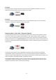
8. Typical Applications 8.1 Ethernet Master (TCP) with multiple serial Slaves (RTU) Application: The Modbus TCP Master is connected to the Ethernet network running Modbus TCP protocol. Serial Modbus devices – running as RTU slaves - are connected to the Ethernet network via the Modbus TCP/RTU Gateway. On Ethernet-side the Modbus Gateway supports up to 16 simultaneous master connections (means 16 Modbus TCP Masters).
8.2 Serial Master (RTU) with serial Slaves (RTU) and Ethernet Slaves (TCP) Application: One serial Master (Modbus RTU/ASCII) and several Modbus RTU Slaves are connected to the serial port of the Modbus Gateway. Ethernet-based Modbus devices (Modbus TCP) – running as slaves - are connected to the Ethernet network. If running operation mode RTU Master only one Modbus RTU Master is allowed.
8.3 Serial Master (RTU) with multiple serial Slaves (RTU) over Ethernet Application: One serial Master (Modbus RTU/ASCII) is connected to the serial port of the Modbus Gateway. At remote side multiple groups of serial Slaves are connected each to a Modbus Gateway. Each Modbus Gateway is able to communicate via Ethernet/Internet with each other. Using this scenario a serial Master can access a serial Modbus control network over long distances by using Ethernet/Internet connections.