
User Documentation

- 4 -
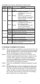
Serial/Ethernet Converter LED Indicators (front panel)
Name
Color
Function
PWR1,
PWR2
Red
Power is being supplied to power input PWR1
or PWR2
Ready
Red
Steady on: Power is on and the
Serial/Ethernet Converter is
booting up.
Blinking: Indicates an IP conflict, the
DHCP or BOOTP server did not
respond properly, or a relay
output occurred.
green
Steady on: Power is on and the
Serial/Ethernet Converter is
functioning normally.
Blinking: The Serial/Ethernet Converter
has been located by the
Administrator’s "Locate" function.
off
Power is off, or a power error condition exists.
E1, E2
orange
10 Mbps Ethernet connection.
green
100 Mbps Ethernet connection.
off
Ethernet cable is disconnected, or has a
short.
P1, P2
orange
Serial port is receiving data.
green
Serial port is transmitting data.
off
No data is being transmitted or received
through the serial port.
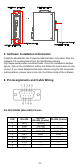
4. Hardware Installation Procedure
STEP 1: After removing the Serial/Ethernet Converter from the box, first
connect the power adaptor. Connect the 12-48 VDC power line
with the terminal block, or connect the DIN-Rail power supply
with the Serial/Ethernet Converter’s terminal block.
STEP 2: Connect the Serial/Ethernet Converter to a network. Use a
standard straight-through Ethernet cable to connect to a Hub
or Switch. When setting up or testing the Serial/Ethernet
Converter, you might find it convenient to connect directly to
your computer’s Ethernet port. Use a cross-over Ethernet
cable If the PC don’t support autocrossing.
STEP 3: Connect the Serial/Ethernet Converter’s serial port to a serial
device.
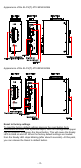
STEP 4: The Serial/Ethernet Converter is designed to be attached to a
DIN-Rail or mounted on a wall. For DIN-Rail mounting, push
down the spring and properly attach it to the DIN-Rail until it
“snaps” into place. For wall mounting, install a wall mount kit
first, and then screw the device onto the wall. The following
figure illustrates the two mounting options: