
User Documentation

Q
UICKSTART
GUIDE
DI350
QS61001049 • 12/2005
Weidmüller Pty Ltd • 43 Huntingwood Drive, Huntingwood NSW 2148
Technical Support Phone + 61 (0) 2 9671 9999 • Fax +61 (0) 2 9671 9900
Email info@weidmuller.com.au • Web www.mannseries.com
Note: Subject to technical alterations without notice
Printed in Australia • QS61001049 • 08/2004
0OWER3UPPLY
%NGINEERING5NITS
#URRENT6OLTAGE
6DC/UT
Installation
General
The DI350 is a 3+1/2 digit indicator for current or voltage signals. It
shows the input measurement in any chosen engineering unit using
bright, 14mm high, LED digits.
Inputs and sensor power supply
The default input is a 4-20mA signal. The DI350 can be ordered to suit
most common analogue current/voltage formats - please check the
model number for details.
As standard the DI350 has a power supply suitable for powering a
loop powered transmitter or other active device as input. This circuit is
completely isolated from the input circuit and power supply.
Warnings:
Check the power supply against the model number before applying power to
the instrument.
These units must only be installed by qualified staff and all relevant
national electrical wiring and safety rules must be followed.
Do not overtighten the mounting screws.
Display scaling (calibration)
General
To set the display scaling you select the decimal point link position and
adjust the ZERO (Z) and SPAN (S) control to give the required units.
The ZERO adjusts the ‘zero’ point reading (adjustment range ±1200
counts). The SPAN adjusts the ‘full scale’ reading (adjustment range 20
to 2100 counts).
Procedure
1. If the decimal point needs to be changed, remove the back plate by
gently prising apart the four clips that hold it in place, place the link (on
the display board) as shown (to right) and reassemble.
2. Inject a ‘zero’ (normally 4mA) signal and adjust the Z control to give
the required display value.
3. Set the input source to ‘full scale’ (normally 20mA) and adjust the S
control to give the required full scale display.
4. Recheck the zero and repeat steps 2 & 3 if required.
Connections
Terminal Signal
1 +24Vdc
Sensor power supply (Output)
2 0V
3 Signal + ve
Analogue Input
4 Signal – ve
5
Not used
6
7 Live (+ve)
Power Supply
8 Neutral (–ve)
m
m
m
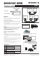
$)©INPUT©CONNECTION©DIAGRAM
4RANSMITTER
LOOP©0OWERED
WIRE
DEVICE
RECEIVING
/THER
OUTPUTS
CURRENTVOLTAGE
$EVICE©WITH
$)
$)
$)©MAIN©BOARD©SHOWING©THE©LOCATION©OF©DECIMAL©POINT©SELECTION©LINKS
!#©POWER©SUPPLY©VOLTAGE©SELECTION©JUMPERS
ON©THE©UNDERSIDE©OF©THE©BOARD
0!.%,©4()#+.%33©©-AX©MM
MM
'!3+%4
MM©MM
#54/54
MM©MM
-OVEABOUTMM
'ENTLYMOVELUGOUTAFRACTIONWITHASCREWDRIVERTORELEASETHEBACKPLATE
0ULLTHEBACKPLATEBACKSLIGHTLYTOKEEPLUGFROMCLICKINGBACKINTOPLACE
2EPEATWITHEACHLUGUNTILBACKPLATECOMESLOOSE