
User Documentation
2583070000/00/04.201826
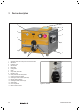
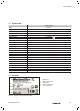
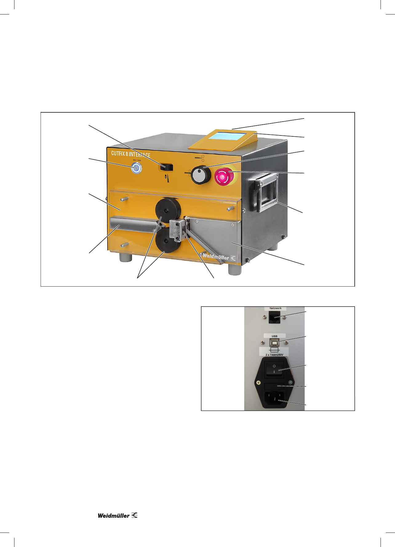
3 Device description
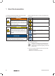
8
5
2
3
4
6
7
1
9
10
11
12
Figure 3.1 Frontal view
1 Adjustment wheel for contact pressure of the feed rollers
2 Start button
3 Protective cover
4 Wire entrance
5 Feed rollers
6 Cutting blade
7 Chute
8 Carry handle, both sides
9 Emergency stop
10 Rotary switch for feed roller position
11 Control unit with touch display
12 USB A-type socket connector (USB stick)
13 External display (optional)
14 USB B-type socket connector (PC)
15 On/Off switch
16 Fuse compartment
17 Mains connection socket
13
14
15
16
17
Figure 3.2 Rear view