
User Documentation


DEUTSCH
Bestimmungsgemäßer Gebrauch
Das elektronische Lastüberwachungssys-
temmaxGUARDdientderselektivenÜber-
last-undKurzschlussüberwachungvon24VDC
Steuerstromkreisen im Umfeld von speicher-
programmierbaren Steuerungen oder ähn-
lichen Steuerungssystemen. Die elektroni-
schen Lastüberwachungsgeräte AMG...EX
(maxGUARD)entsprechenderSchutzklasse
IP20(gemäßIEC60529)undkönnenimexplosi-
ongefährdetenBereichZone2(gemäßRichtlinie
2014/34/EU)sowieimsicherenBereicheinge-
setzt werden. Die elektronischen Lastüberwa-
chungsgeräte dienen dem Leitungsschutz. Der
Leiterquerschnitt ist entsprechend der internen
Sicherung zu bemessen.
EinLastüberwachungsgerätAMGELM-xFEX
kann nur zusammen mit einem passiven Ein-
speisegerät(AMGFIM-0)inVerbindungmitei-
nem Steuergerät (AMG CM EX) oder einem ak-
tivenEinspeisegerät(AMGFIM-CEX)betrieben
werden.
DerBetriebmussmiteiner24VDC
(18...30VDC)Stromversorgungerfolgen,dieei-
ne Schutzkleinspannung (SELV) oder Funktions-
kleinspannung mit sicherer Trennung (PELV) lie-
fert.WeidmüllerStromversorgungsgeräte,wie
z.B.PROtop,PROmaxundPROeco,stellen
das sicher.
EinausreichenderSchutzgegendasBerühren
von spannungsführenden Teilen sowie gegen
das Eindringen von Staub und Wasser ist durch
den Einbau in ein geeignetes Gehäuse sicherzu-
stellen(z.B.Schaltschrank,Steuerkasten,Kon-
sole o. ä.).
ZurKontaktvervielfältigungdesLastüberwa-
chungsausgangs können die EX Potentialvertei-
lerdermaxGUARD-Familieverwendetwerden.
HierzusindausschließlichdieWeidmüllerQuer-
verbinder ZQV 4N einzusetzen.
Vor der Installation ist die elektrische
Anlage allseitig spannungslos zu schal-
ten und Spannungsfreiheit festzu-
stellen.
Das Gerät darf nur von einer Elektro-
fachkraftinstalliertwerden,diemitden
nationalen und internationalen Geset-
zen,VorschriftenundStandardsver-
traut ist.
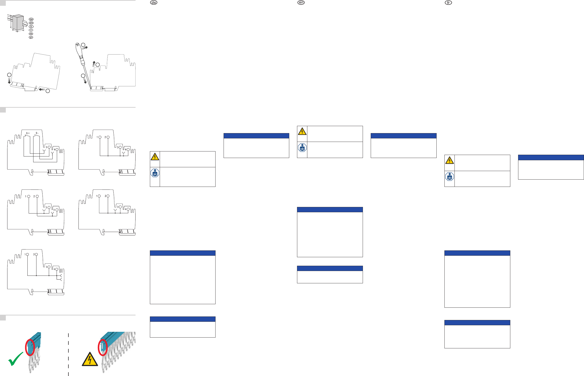
Montage und Demontage
► RastenSiedasGerätaufeine35mmDIN-
Tragschiene(z.B.WeidmüllerTS35x7,5)
(siehe Abb. A1).
► DemontierenSiedasGerät,indemSieden
RastfußmiteinemSchraubendreherentrie-
geln (siehe Abb. A2).
Installation
Die elektrische Anlage ist nach den allgemei-
nenRegelnderElektrotechnikvonqualizier-
tem Fachpersonal zu errichten. Dies umfasst ins-
besondere:
• den Schutz gegen elektrischen Schlag
• die ausreichenden Dimensionierung der Siche-
rungen und Anschlussleitungen
• eineausreichendenKonvektion
ACHTUNG
Gefahr der Fehlfunktion!
► Schalten Sie nicht mehrere Lastüberwa-
chungsgeräte parallel oder hintereinander.
► StellenSiedenBerührungsschutzIP20
dadurchsicher,dassSiedieLastüber-
wachungsstation beidseitig mit je einer
Endplatte (AMG EP) und einem Endwinkel
(WEW35/2V0GFSW)abschließen,sie-
he Seite 1.
Zerstörungsgefahr!
► StellenSiesicher,dassdieAusgangsspan-
nung nicht dauerhaft höher ist als die Ein-
gangsspannung.
► Verwenden Sie einen geeigneten Schrauben-
dreher (siehe Angabe in der Tabelle „Techni-
sche Daten“).
ACHTUNG
Zerstörungsgefahr bei Falschpolung!
► SchließenSiedasGerätpolrichtigan.
► Prüfen Sie den festen Sitz aller Anschluss-
leitungen.
Funktionsbeschreibung
DerPotentialverteilerdientderKontaktverviel-
fältigungderPlus-undMinusausgängedes
Lastüberwachungsgerätes.
BeidenPotentialverteilern
AMG MD/OD/PD/DIS EX erfolgt die Potentialzu-
führungausschließlichüberQuerverbindervon
den Ausgängen der Lastüberwachungsgeräte.
Der Potentialverteiler AMG XMD EX ist intern mit
dem Hauptstrang des Minuspotentials verbunden.
Der Potentialverteiler AMG DIS EX ist mit einer
TrenneinrichtungfürdenMinus-undPlusaus-
gang ausgestattet.
Verwendung von Querverbindern
BeiLastüberwachungsstationenmitStrömen
> 20 A müssen die Querverbindungskanäle der
beidenHauptstränge(Plus-undMinuspotential)
doppelt bestückt werden. Insbesondere bei um-
fangreicheren Lastüberwachungsstationen kann
eine Verlängerung der Querverbindung notwen-
dig sein. Die Markierungen am Querverbindungs-
kanal kennzeichnen die elektrisch bestückten
Doppelkontakte. Eine Verlängerung der Querver-
bindungkannnuraufdiesenKontaktenvorge-
nommenwerden.BeilangenLastüberwachungs-
stationenempehltsicheineVerschachtelungder
Querverbinder im Doppelkanal.
► VerwendenSieimBereichderQuerverbin-
dungskanäle der Lastüberwachungsausgänge
vollisolierte Querverbinder mit den Polzahlen
2...10 (siehe Abb. C).
► BeihöherenPolzahlenkönnenSieeinen
50-poligenQuerverbinderverwenden,denSie
bedarfsgerecht ablängen.
ACHTUNG
Kurzschlussgefahr durch nicht isolierte
Querverbinder!
► FügenSieüberalldort,woblankeSchnitt-
kantenaneinanderstehen,dieTrennwand
AMG PP ein.
ENGLISH
Intended use
ThemaxGUARDelectronicloadmonitoringsys-
temisusedfortheselectiveoverloadandshort-
circuit monitoring of 24 V DC control circuits in
theeldofprogrammablecontrollersorsimilar
controlsystems.TheAMG...EX(maxGUARD)
electronic load monitoring devices comply with
safetyclassIP20(inaccordancewithIEC60529)
andcanbeusedbothinapotentiallyexplosive
atmosphere in Zone 2 (in accordance with Direc-
tive2014/34/EU),aswellasinasafezone.Elec-
tronic load monitoring devices are used for line
protection.Thewirecross-sectionhastobedi-
mensioned according to the internal fuse.
TheloadmonitoringdeviceAMGELM-xFEXcan
only be operated together with a passive pow-
er-feeddevice(AMGFIM-0)inconjunctionwitha
controldevice(AMGCMEX)oranactivepower-
feeddevice(AMGFIM-CEX).
The system must be operated with a 24 V DC
(18...30VDC)safetyextra-lowvoltage(SELV)or
protectiveextra-lowvoltage(PELV)powersupply
with safe disconnection. Weidmüller power sup-
plydevices,e.g.PROtop,PROmaxandPROe-
co,ensurethis.
Installation in a suitable enclosure provides ad-
equate protection against contact with live parts
and also against the ingress of dust and water
(e.g.electricalcabinet,panel,consoleorsimilar).
ThemaxGUARDfamilyEXpotentialdistributors
can be used for contact multiplication of the load
monitoring output. Only Weidmueller ZQV 4N
cross-connectorscanbeusedforthispurpose.
Beforeinstallingtheelectricalsystem,
it should be completely disconnected
from the mains and the absence of volt-
age must be proven.
The device must only be installed by
qualiedelectricianswhoarefamil-
iarwithnationalandinternationallaws,
provisions and standards.
Mounting and demounting
► Clip the device on to a 35 mm DIN mounting
rail(e.g.WeidmüllerTS35x7.5,seeFig.A1).
► Dismantlethedevicebyreleasingtheclip-in
foot using a screwdriver (see Fig. A2).
Installation
The electrical system must be installed in accord-
ance with the general rules of electrical engineer-
ingandbyqualiedspecialists.Thisincludes:
• protection against electric shock
• correct sizing of fuses and connecting lines
• sufcientconvection
ATTENTION
The risk of malfunction!
► Donotconnectmultipleload-monitoringde-
vices in parallel or in series.
► Ensuretouch-safeprotectionIP20byter-
minating the load monitoring station with
an end plate (AMG EP) and an end bracket
(WEW 35/2 V0 GF SW) at each of the two
ends,seepage1.
Risk of destruction
► Make sure that the output voltage is not
higher than the input voltage on a perma-
nent basis.
► Use of a suitable screwdriver (see information
contained in the “technical data” table).
ATTENTION
Risk of destruction if polarity is incorrect!
► Connect the device with the correct polarity.
► Checkthecorrecttofallconnectinglines.
Functional description
The potential distributor is used for contact mul-
tiplication of the positive and negative outputs of
the load monitoring unit.
With the AMG MD/OD/PD/DIS EX potential dis-
tributors,distributionitselfisachievedexclusively
bymeansofcross-connectorsfromtheoutputsof
the load monitoring devices.
The AMG XMD EX potential distributor is inter-
nally connected with the main line of the nega-
tive potential.
The AMG DIS EX potential distributor is equipped
with a separating device for the negative and
positive outputs.
Use of the cross-connectors
In the case of load monitoring stations with cur-
rents>20Ayoumustassemblethecross-con-
nection channels of the two main strands (plus
and minus potential) twice over. The cross con-
nectorsmayneedtobeextended,particularlyin
thecaseofextensiveloadmonitoringstations.
Themarkingsonthecross-connectchannelindi-
cate the electrically assembled twin contacts. You
can prolong the cross connection only on these
contacts. In the case of very long load monitoring
stationswerecommendinterlacingcross-con-
nectors in the double channel.
► Inthecross-connectionchannelareaofthe
loadmonitoringoutputs,usefullyinsulated
cross-connectorswithnumberofpolesbe-
tween 2 and 10 (see Fig. C).
► Withhighernumberofpoles,a50-polecross-
connector can be used and cut to length as
required.
ATTENTION
Risk of short circuit due to non-insulated
cross-connector!
► Fit the separation plate AMG PP wherev-
erthereareblankcuttingedgesnextto
one another.
FRANÇAIS
Utilisation prévue
Lesystèmedesurveillanceélectroniquedela
chargemaxGuardaétéconçupoursurveillerles
surchargessélectivesainsiquelescourts-circuits
des circuits de commande de 24 V DC dans le
domaine des contrôleurs programmables ou tout
systèmedecommandesimilaire.Lesdispositifs
de surveillance électronique de la charge AMG...
EX(maxGUARD)sontconformesàlaclassede
protectionIP20(selonlanormeCEI60529)et
peuventêtreutilisésdansuneatmosphèrepo-
tentiellementexplosiveenzone2(selonladirec-
tive2014/34/UE),ainsiquedansunezonedesé-
curité. Les dispositifs de surveillance électronique
de la charge sont utilisés pour la protection des
lignes. La section du conducteur doit être dimen-
sionnée selon le fusible interne.
L’appareil de surveillance de charge
AMGELM-xFEXnepeutfonctionnerqu’en
association avec un appareil d’alimentation
passif(AMGFIM-0)etunappareildecom-
mande (AMG CM EX) ou d’alimentation actif
(AMGFIM-CEX).
Lesystèmedoitêtreutiliséavecunealimenta-
tionélectriqueàtrèsbassetensiondesécuri-
té(TBTS)ouàtrèsbassetensiondeprotection
(TBTP)de24VDC(18...30VDC)àdébran-
chementable.Lesalimentationsélectriques
WeidmüllerPROtop,PROmaxetPROeco,par
exemple,garantissentcesexigences.
L’installationdansunboîtieradapté(p.ex.une
armoireélectrique,unboîtierdecommande,une
console,etc.)protègedemanièreadéquatede
toutcontactavecdescomposantssous-tension
etcontretouteinltrationd’eauetdepoussière.
Les distributeurs de potentiel EX de la gamme
maxGUARDpeuventêtreutiliséspourmulti-
plier les contacts de la sortie de surveillance
de charge. Seuls les connecteurs transver-
sauxWeidmüllerZQV4Npeuventêtreutilisés
àcetten.
Avantdeprocéderàl’installation,le
systèmeélectriquedoitêtremishors
tension et l’absence de tension doit être
contrôlée.
L’appareil ne doit être installé que par
un électricien ayant une bonne connais-
sancedeslois,directivesetnormesna-
tionales et internationales.
Montage et démontage
► Fixezl’appareilsurunrailDIN35mm(p.ex.
WeidmüllerTS35x7,5,voirFig.A1).
► Démontez l’appareil en détachant le pied
encliquetableàl’aided’untournevis(voir
Fig. A2).
Installation
Lesystèmeélectriquedoitêtreinstallépardes
spécialistesqualiésdanslerespectdesrègles
générales de l’électrotechnique.
Cela comprend :
• une protection contre les chocs électriques
• un dimensionnement approprié des fusibles et
câblesderaccordement
• lamiseàdispositiond’uneconvectionsuf-
sante
ATTENTION
Risque de dysfonctionnement !
► Ne connectez pas plusieurs appareils de
surveillancedelachargeenparallèleou
en série.
► VeillezàlaprotectionautoucherIP20en
assurant la terminaison de la station de
surveillancedelachargeavecuneasque
de fermeture (AMG EP) et une équerre de
blocage(WEW35/2V0GFSW)àchacune
desdeuxextrémités,voirpage1.
Risque de destruction !
► Veillezenpermanenceàcequelaten-
sion de sortie ne dépasse pas la tension
d’entrée.
► Veuillez utiliser un tournevis adapté (consul-
ter les informations contenues dans le tableau
« caractéristiques électriques »).
ATTENTION
Risque de destruction si la polarité est in-
correcte !
► Connectez l’appareil en respectant la po-
larité.
► Vériezquetouslescâblesderaccorde-
ment soient correctement placés.
Description fonctionnelle
Le distributeur de potentiel est utilisé pour la mul-
tiplication de contacts des sorties positive et né-
gative de l’unité de surveillance de charge.
Avec les distributeurs de potentiel
AMGMD/OD/PD/DISEX,ladistributionmême
est réalisée uniquement par le biais des connec-
teurstransversauxsituésauniveaudessorties
des appareils de surveillance de charge.
Le distributeur de potentiel AMG XMD EX est
connectéeninterneaveclecâbleprincipaldupo-
tentiel négatif.
Le distributeur de potentiel AMG DIS EX est équi-
pé d’un appareil de séparation pour les sorties
négative et positive.
Utilisation des connecteurs transversaux
Lorsque les courants des stations de surveil-
lancedechargesontsupérieursà20A,vousde-
vezéquiperlescanauxdeconnexiontransver-
saledesdeuxbrinsprincipaux(potentielpositif
et négatif) en double. Les connecteurs transver-
sauxpeuventnécessiteruneextension,parti-
culièrementpourlesstationsdesurveillancede
charge étendues. Les repérages sur le canal de
connexiontransversalecaractérisentlescontacts
doubleséquipésdemanièreélectrique.Vous
pouvezprolongerlaconnexiontransversaleuni-
quement au niveau de ces contacts. Dans le cas
delonguesstationsdesurveillancedecharge,
nous recommandons d’entrelacer les connec-
teurstransversauxdanslecanaldouble.
► Danslazonedesvoiesdeconnexiontrans-
versale des sorties de surveillance de la
charge,utilisezdesconnecteurstransver-
sauxtotalementisolésdotésde2à10pôles
(voir Fig. C).
► Silenombredepôlesestsupérieur,ilestpos-
sible d’opter pour un connecteur transver-
saldotéde50pôlesetdelecouperàlalon-
gueur requise.
ATTENTION
Risque de court-circuit en cas de connec-
teur transversal non isolé !
► InsérezleséparateurAMGPPàn’importe
quelemplacementoùdesarêtesdecoupe
dénudéessontcoteàcote.
Montage und Demontage / Mounting and demounting / Montage et démontage /
Montaggio è smontaggio / Montaje y desmontaje / 安装和拆卸
A
Blockschaltbild und Anschlussbelegung / Block diagram and electrical connections /
Schéma fonctionnel et raccordements/ Diagramma a blocchi e assegnazione dei
collegamenti / Esquema eléctrico y asignación de conexión / 和电气连接方块图
B
Querverbinder / Cross-connector / Connecteur transversal / Collegamento trasversale /
Conexión transversal / 横向联接器
C
a / b / c
Höhe/Breite/Tiefe
Height / Width / Depth
Hauteur / Largeur / Profondeur
Altezza/Larghezza/Profondità
Altura / Ancho / Profundidad
高/宽/深
a
bc
1
2
1
2
3
Abb. / Fig. A1 Abb. / Fig. A2
AMG OD EX
AMG XMD EX
AMG DIS EX AMG MD EX
AMG PD EX
ZQV 4N
50 pol.
ZQV 4N
2...10 pol.