
User Documentation
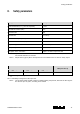
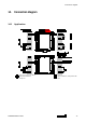
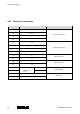

Table Of Contents
- 1.1 Revision history
- 1.2 Validity
- 1.3 Contact address
- Table of contents
- 2. Observed standards
- 3. Acronyms and abbreviations
- 4. Purpose of the product
- 5. Assumptions and restrictions for use of the product
- 6. Functional specification of the safety functions
- 7. Functional specification of the non-safety functions
- 8. Safety parameters
- 9. Failure category SIL 2
- 10. Hardware and software configuration
- 11. Periodic proof test procedure
- 12. Procedures to repair or replace the product
- 13. Maintenance
- 14. Connection diagram
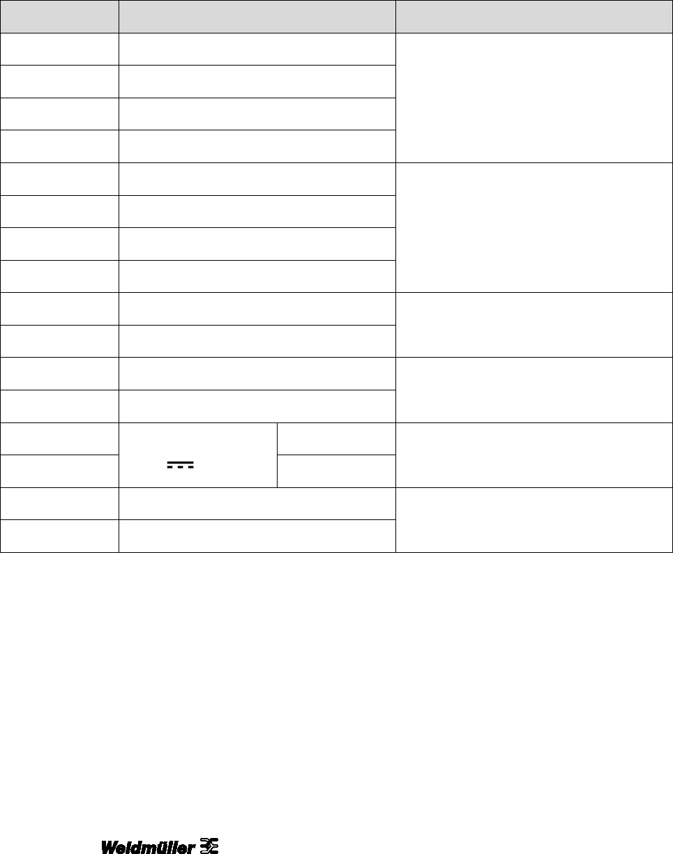
Connection diagram
18 1482850000/01/11.2017
14.2 Electrical connections
Terminal
Function
Connector
11
Out –
Ex output channel 1
12
Out +
13
14
21
Out –
Ex output channel 2
22
Out +
23
24
41
In –
input channel 1
42
In +
43
In –
input channel 2
44
In +
51
19.2…31.2 V
3 W
GND
power supply
52
+
53
NC
status relay
54
COM