ACT20X-(2)HTI-(2)SAO Temperature/mA converter Safety Manual
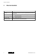
1.1 Revision history Version Date Change 00 04/2014 First Edition 01 11/2017 Products added 1.2 Validity This manual is valid for the following products: Device Type version Order number 2 ACT20X-HTI-SAO-S 8965470000 2 ACT20X-2HTI-2SAO-S 8965480000 2 ACT20X-HTI-SAO-P 2 ACT20X-2HTI-2SAO-P 2456190000 1.3 Contact address 2456180000 Weidmüller Interface GmbH & Co. KG Klingenbergstraße 16 32758 Detmold Germany T +49 5231 14-0 F +49 5231 14-292083 www.weidmueller.com 1482900000/01/11.
Table of contents Table of contents 1.1 Revision history ................................................................................................................................ 3 1.2 Validity ................................................................................................................................................ 3 1.3 Contact address ................................................................................................................................
Table of contents 14. Configuration with FDT/DTM .............................................................................. 19 14.1 Concept ............................................................................................................................................ 19 14.2 Hardware / Firmware ....................................................................................................................... 19 15. Parameterization by user interface..............................
Observed standards 2. Observed standards Standard Description IEC 61508 Functional safety of electrical / electronic / programmable electronic safetyrelated systems IEC 61508-2:2000 Part 2: Requirements for electrical / electronic / programmable electronic safety-related systems IEC 61508-3:1998 Part 3: Software requirements IEC 61326-3-1:2008 Immunity requirements for safety-related systems 6 1482900000/01/11.
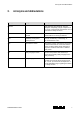
Acronyms and abbreviations 3. Acronyms and abbreviations Acronym / Abbreviation Designation Element Description Term defined by IEC 61508 as “part of a subsystem comprising a single component or any group of components that performs one or more element safety functions”. PFD Probability of Failure on Demand This is the likelihood of dangerous safety function failures occurring on demand.
Purpose of the product 4. Purpose of the product The ACT20X-HTI-SAO is an one channel, the ACT20X-2HTI-2SAO is a two channel temperature transducer for transmission of signals to the safe area from temperature sensors (Pt, Ni and TC) or current sources installed in the hazardous area. The device can be mounted in the safe area and in Zone 2 / Division 2 and receive signals from Zone 0, 1, 2, 20, 21, 22 and mines or Class I/II/III, Division 1, Group A-G.
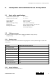
Assumptions and restrictions for use of the product 5. Assumptions and restrictions for use of the product 5.1 Basic safety specifications Operational temperature range: -20...+60 °C Storage temperature range: -20...+85 °C Power supply type: Double or reinforced Supply voltage: 19.2...31.2 V DC External loop supply voltage 5...26 V DC + external drop Mounting area: Zone 2 & Class I, Division 2 or safe area Mounting environment: Pollution degree 2 or better, Overvoltage category II 5.
Assumptions and restrictions for use of the product 5.3 Associated equipment 5.3.1 RTD sensor wiring If a 2-wire or a 3-wire connection for RTD is selected, the end user must ensure that the applied sensor wiring does not introduce failures exceeding the requirements for the safety application. 5.3.2 Sensor errors If Sensor error detection is disabled, if current input range 0...
Functional specification of the safety functions 6. Functional specification of the safety functions Conversion of current signals (0...20 mA or 4...20 mA), RTD sensor signals or thermocouple sensor signals from hazardous areas to a 4...20 mA current output signal, in two separately configurable channels, within specified accuracy. For RTD sensors, cable resistances of up to 50 Ω per wire can be compensated if a 3- or 4-wire connection is configured.
Functional specification of the non-safety functions 7. Functional specification of the non-safety functions The status relay (terminal 53 and 54) and LED outputs are not suitable for use in any Safety Instrumented Function. 12 1482900000/01/11.
Safety parameters 8. Safety parameters Safety parameter Ex input SIL2 Proof-test interval (Tproof), (10 % of loop PFD) 3 years Safe Failure Fraction (SFF) 90.7 % Demand response time, opto output Signal input: Temperature input: Demand mode High Demand rate 3000 s Diagnostic test interval 30 s Mean Time To Repair (MTTR) 24 h Hardware Fault Tolerance (HFT) 0 Component type B SIL capability SIL 2 Description of the “safe state” Output ≤ 3.6 mA or output ≥ 21 mA < 0.5 s < 1.
Failure category SIL 2 9. Failure category SIL 2 Failure rates according to IEC 61508 Total failure rate for dangerous detected failures (λDD) 367 FIT Total failure rate for dangerous undetected failures (λDU) 61 FIT Total failure rate for all safe failures (λSafe) 234 FIT -9 -1 FIT = 10 h (Failure in time) 14 1482900000/01/11.
Hardware and software configuration 10. Hardware and software configuration All configurations of software and hardware versions are fixed from factory and cannot be changed by enduser or reseller. This manual only covers products labeled with the product version (or range of versions) specified on the front page. 1482900000/01/11.
Periodic proof test procedure 11. Periodic proof test procedure Step Action 1 Bypass the safety PLC or take other appropriate action to avoid a false trip. 2 Connect a simulator identical to the input setup. 3 Apply input value corresponding to 0/100 % output range to each channel. 4 Observe whether the output channel acts as expected. 5 Restore the input terminals to full operation. 6 Remove the bypass from the safety PLC or otherwise restore normal operation.
Procedures to repair or replace the product 12. Procedures to repair or replace the product Any failures that are detected and that compromise functional safety should be reported to the sales department at Weidmüller Interface GmbH & Co. KG. Repair of the device and replacement of circuit breakers must be done by Weidmüller Interface GmbH & Co. KG only. 1482900000/01/11.
Maintenance 13. Maintenance No maintenance required. 18 1482900000/01/11.
Configuration with FDT/DTM 14. Configuration with FDT/DTM The temperature transducer ACT20X-(2)HTI-(2)SAO will be configured via PC according to the FDT/DTM standard. 14.1 Concept The FDT technology standardizes the configuration and communication interfaces between different devices and connected systems, IEC 62453. Therefore the FDT provides a common environment for accessing and connecting the devices features.
Parameterization by user interface 15. Parameterization by user interface Configuration of the parameter via the General User interface "GUI" via the FDT / DTM software. The parameterization according to the safety requirements is oriented towards the general using the product related DTM (Figure 2 "GUI DTM configuration (1) (example)" and Figure 3 "GUI DTM configuration (2) (example)" shows an example of a DTM). Figure 2: 20 GUI DTM configuration (1) (example) 1482900000/01/11.
Parameterization by user interface Figure 3: GUI DTM configuration (2) (example) 1482900000/01/11.
SIL concept for DTMs 16. SIL concept for DTMs 16.1 Activate/deactivate safe parameterization In online mode of the DTM the user can directly configure the device and / or the offline parameterization at the PC. For the SIL configuration the user shall shown “Change SIL state” in the additional functions of each DTM. The function is only available in online state and the hardware is verified, according Figure 4 "SIL configuration (example)". Figure 4 22 SIL configuration (example) 1482900000/01/11.
SIL concept for DTMs By activate the SIL configuration all other parameter views and functions are disabled (and closed) and vice versa, according to Table 1 "Function against SIL".
SIL concept for DTMs By executing the SIL function the DTM request the SIL-state and the user has to enter the password. The SIL-state and the password (enable and password) are defined in open and lock, see Figure 5 "GUI SIL configuration (OPEN) (example)" and Figure 9 "GUI SIL configuration (LOCK) (example)". Figure 5: GUI SIL configuration (OPEN) (example) To deactivate the SIL state the user has to enter the same password and confirm it to change the SIL state from locked to open.
SIL concept for DTMs Figure 6: Valid configuration check (example) 1482900000/01/11.
SIL concept for DTMs 16.2 Verification procedure The configuration is re-load from the device and shown in a DTM GUI (Graphical User Interface). The user interface loaded the image (as image) with the loaded configuration in the same window. The user now sees a GUI with the configuration loaded from the device, the entered configuration (device parameters) and the stored image (written parameters) as a configuration and will be prompted to check the configuration.
SIL concept for DTMs The user must compare each parameter from the “read back device parameters” side with the “Previously written paramers as image”. To accept the parameters the user must press the “Next” button. After that the next window with a parameter set will show and must accept by the user. If all parameters are compared by the user, the configuration software shows the screen below.
SIL concept for DTMs The GUI for SIL configuration is continues read the SIL state and shall shown the change from “OPEN” to “LOCK”, see Figure 9 "GUI SIL configuration (LOCK) (example)". If the configuration is corrupted, then the devices rejected the configuration and change the state to “FAIL”. After successful locking the configuration the user get a list of all parameter from the DTM and from the stored image file.
SIL concept for DTMs 16.3 Configuration of a SIL active product If the user would like to reconfigure a SIL activated product the software will show the message below. Figure 10: SIL active 1482900000/01/11.
SIL concept for DTMs To do a reconfiguration, the user needs to deactivate the SIL mode as described in chapter 16.1 "Activate/deactivate safe parameterization" on page 22. Then all parameters are available and can configure. Figure 11: 16.4 Locked SIL state after configuration Changing SIL password The user can change the SIL password in the SIL “OPEN” state, when the user type a new password and confirm it.
SIL concept for DTMs 16.5 Safety-related configuration user responsibility 16.5.1 Safety-related configuration parameters (channel 1) Input Tab Name Function Channel tag and type Selected input type: Temperature Current Current range Selected fixed input range for current measurements (for channel tag and type = current): 0...20 mA (no sensor error detection!) 4...
SIL concept for DTMs Selectable TC sensor types (for channel tag and type = TC): type B type E type J type K type L type N type R type S type T type U type W3 type W5 type Lr CJC type for (for channel tag and type = TC): Internal CJC = internal CJC sensor measurement External CJC = connector measurement (accessory) Temperature unit Selected temperature unit (for channel tag and type = current): Celsius Fahrenheit Temperature limits Selected temperature unit (for channel tag and type = temperature) Low =
SIL concept for DTMs The end user must ensure that the applied sensor including wiring has a failure rate qualifying it for the safety application without the detection enabled. Downscale (0 mA) = output is 0 mA at sensor error Downscale (3.5 mA) = output is 3.5 mA at sensor error (NE43 downscale) Upscale (23 mA) = output is 23 mA at sensor error (NE43 upscale) RESP 1482900000/01/11.2017 Analogue output response time in seconds: Range is 0.0 to 60.
SIL concept for DTMs 16.5.2 Safety-related configuration parameters (channel 2) (only for ACT20X-2HTI-2SAO) Input Tab Name Function Channel tag and type Selected input type: Temperature Current Current range Selected fixed input range for current measurements (for channel tag and type = current): 0...20 mA (no sensor error detection!) 4...
SIL concept for DTMs Selectable TC sensor types (for channel tag and type = TC): type B type E type J type K type L type N type R type S type T type U type W3 type W5 type Lr CJC type for (for channel tag and type = TC): Internal CJC = internal CJC sensor measurement External CJC = connector measurement (accessory) Temperature unit Selected temperature unit (for channel tag and type = current): Celsius Fahrenheit Temperature limits Selected temperature unit (for channel tag and type = temperature): Low
SIL concept for DTMs The end user must ensure that the applied sensor including wiring has a failure rate qualifying it for the safety application without the detection enabled. Downscale (0 mA) = output is 0 mA at sensor error Downscale (3.5 mA) = output is 3.5 mA at sensor error (NE43 downscale) Upscale (23 mA) = output is 23 mA at sensor error (NE43 upscale) Analogue output response time in seconds: Range is 0.0 to 60.0 s RESP 16.5.
Fault reaction and restart 17. Fault reaction and restart When the ACT20X-(2)HTI-(2)SAO detects a fault the output will go to Safe State, in which the output will go to“de-energised”. If the fault is application-specific (cable error detection) the device will restart when the fault has been corrected. For device faults there are 2 ways of bringing the module out of Safe State. 1. Power cycle the module. 2. Bring the module out of SIL mode (refer to chapter 16.
Connection diagram 18. Connection diagram 18.1 38 Application 1482900000/01/11.
Connection diagram 18.2 Electrical connections Function Terminal RTD Connector mA TC 2W 11 3W 4W Sense – Sense – 12 – R R– R– 13 + R R+ R+ + – Ex input channel 1 14 Sense + 21 Sense – Sense – 22 – R R– R– 23 + R R+ R+ + – Ex input channel 2 24 Sense + 41 Out – 42 Out + 43 Out – 44 Out + 51 GND 52 +24 V DC 53 NC 54 COM output channel 1 output channel 2 power supply status relay 1482900000/01/11.
Connection diagram 40 1482900000/01/11.
Weidmüller Interface GmbH & Co. KG Klingenbergstraße 16 32758 Detmold Germany T +49 5231 14-0 F +49 5231 14-292083 www.weidmueller.com Order Number: 1482900000/01/11.