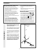
® Model No. WESY87100 Serial No. (Write the serial number in the space above for reference.) USER’S MANUAL Class H C Fitness Product Serial Number Decal QUESTIONS? As a manufacturer, we are committed to providing complete customer satisfaction. If you have questions, or find that there are missing or damaged parts, we will guarantee you complete satisfaction through our Customer Service Department. Please CALL: 0345-089009 Or WRITE: ICON Fitness Lifestyle Ltd.
TABLE OF CONTENTS IMPORTANT PRECAUTIONS . . . . . . . . . . . . . . . . . . . . . . . . . . . . . . . . . . . . . . . . . . . . . . . . . . . . . . . . . . . . .3 BEFORE YOU BEGIN . . . . . . . . . . . . . . . . . . . . . . . . . . . . . . . . . . . . . . . . . . . . . . . . . . . . . . . . . . . . . . . . . . .4 ASSEMBLY . . . . . . . . . . . . . . . . . . . . . . . . . . . . . . . . . . . . . . . . . . . . . . . . . . . . . . . . . . . . . . . . . . . . . . . . . . .5 ADJUSTMENT . . . . . . . . . . . . .
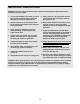
IMPORTANT PRECAUTIONS WARNING: To reduce the risk of serious injury, read the following important precautions before using the home gym system. 1. It is the responsibility of the owner to ensure that all users of the home gym system are adequately informed of all precautions. 9. Always stand on a foot plate when performing an exercise that could cause the home gym system to tip. 2. Read all instructions in this manual and in the accompanying literature before using the home gym system. 10.
BEFORE YOU BEGIN have additional questions, please call our Customer Service Department at 0345-089009. To help us assist you, please note the product model number and serial number before calling. The model number is WESY87100. The serial number can be found on a decal attached to the WEIDER® 8510 (see the front cover of this manual). Thank you for selecting the versatile WEIDER® 8510 Home Gym System.
ASSEMBLY • As you assemble the home gym system, be sure that all parts are oriented as shown in the drawings. Before beginning assembly, carefully read the following information and instructions: • Place all parts of the home gym system in a cleared area and remove the packing materials; do not dispose of the packing materials until assembly is completed. • Tighten all parts as you assemble them, unless instructed to do otherwise.
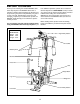
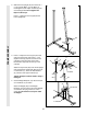
2. Slide the Front Upright (42) onto the 5/16” x 2 1/2” Carriage Bolts (1) in the Base (4). Hand tighten a 5/16” Nylon Locknut (3) onto each Carriage Bolt. Do not tighten the Nylon Locknuts yet. 2 Press a 1” Square Inner Cap (65) into the Front Upright (42). 42 65 FRAME ASSEMBLY 3 4 1 3. Press a 2” Square Inner Cap (27) into each end of the Top Frame (55). Press a 1 3/4” Square Inner Cap (44) into each end of the crossbar on the Top Frame.
5. Press the Weight Tube Bumper (64) into the end of the Weight Tube (63). Insert the Weight Tube into the stack of Weights (25). Be sure that the pins on the Weight Tube are resting in the pin grooves in the upper Weight. 5 Holes Lubricate the insides of the holes in the Top Weight (76). Set the Top Weight onto the stack of Weights (25). 62 Insert both Weight Guides (62) into the stack of Weights (25). Be sure that the holes in the Weight Guides are at the top, as shown.
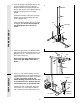
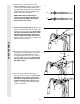
. Press a 1 3/4” Square Inner Cap (44) into the top of a Press Arm (46). Press a 1” Round Inner Cap (49) into each end of the handle on the Press Arm. Attach the Press Arm to one side of the Press Frame (17) with two 5/16” x 2 1/2” Bolts (22) and two 5/16” Nylon Locknuts (3). 8 44 49 44 49 46 49 46 Assemble the other Press Arm (46) in the same manner. 22 3 17 9. Identify the Right Arm (48) and the Left Arm (47). Note the position of the welded bracket on each Arm.
11. During steps 11 through 25, refer to the CABLE DIAGRAM on page 21 of this manual to verify proper cable routing. Before beginning this section, identify the Long Cable (23) and the Short Cable (58) by comparing the lengths and ends of the cables. 11 23 IMPORTANT: Whilst assembling the cables, do not overtighten the bolts and nuts securing the pulleys. The pulleys must be able to turn freely. 58 CABLE ASSEMBLY 12. Locate the Long Cable (23).
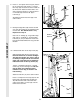
15. Route the Long Cable (23) around the “V”Pulley (6) on the Right Arm (48). Be sure that the Cable is in the groove of the “V”Pulley and that the Long Cable Trap (50) is turned to hold the Cable in place. Tighten the 3/8” x 2 1/2” Bolt (7) and the 3/8” Nylon Locknut (not shown). 15 50 7 6 48 23 CABLE ASSEMBLY 16. Route the Long Cable (23) around the 3 1/2” Pulley (15) attached to the Pulley Bracket (20).
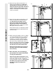
19. Note: This assembly step shows how to complete the assembly of several preattached parts. 19 The 5/8” x 9/16” Spacer (73) has been preattached on the outside of the 3 1/2” Low Pulley (77) for shipping purposes. Remove the 3/8” Nylon Locknut (21), the Spacer, and the Pulley from the 3/8” x 3 3/4” Bolt (71). Do not remove the Bolt. The Bolt has been shown removed for part identification. Reattach the 3 1/2” Low Pulley (77), with the 5/8” x 9/16” Spacer (73) between the Pulley and the Press Frame (17).
21. If the indicated 3 1/2” Pulley (15) is preattached to the Front Upright (42), remove it. Route the Short Cable (58) around the Pulley. Attach the Pulley and two Pulley Covers (78) to the lower hole in the Front Upright with the 3/8” Nylon Jam Nut (81), the 3/8” Flat Washer (9) and the 3/8” x 3 3/4” Bolt (71). 21 42 71 78 15 58 81 22 CABLE ASSEMBLY 22. Route the Short Cable (58) around the 3 1/2” Pulley (15) attached to the upper hole in the Press Frame (17).
24. Attach the end of the Short Cable (58) to the Long “U”-Bracket (57) with a 1/4” Nylon Locknut (2) and a 1/4” Flat Washer (10). Do not completely tighten the Nylon Locknut. It should be threaded onto the end of the Cable so only a couple of threads are showing above the nut, as shown in the inset drawing. 24 2 57 10 58 CABLE ASSEMBLY 2 10 57 25. Attach the Long Cable (23) to the Small “U”Bracket (67) with a 1/4” Nylon Locknut (2) and a 1/4” Flat Washer (10).
26. Attach the Backrest (41) to the Front Upright (42) with two 1/4” x 2 1/2” Screws (43) and two 1/4” Flat Washers (10). 26 42 41 SEAT ASSEMBLY 43 10 27. Press a 1 1/2” Square Inner Cap (32) into the Seat Frame (36). 27 13 Insert the 1/4” x 2” Carriage Bolt (38) into the centre hole in the Seat Plate (37). Attach the Seat Plate to the Seat (13) with two 1/4” x 3/4” Screws (18). Insert the 1/4” x 2” Carriage Bolt (38) into the indicated hole in the Seat Frame (36).
29. Rest the Seat Frame (36) on the indicated pin in the Front Upright (42). Attach the Seat Frame to the Front Upright with a 5/16” x 2 3/4” Carriage Bolt (14) and the Seat Knob (40). 29 40 36 14 Pin SEAT ASSEMBLY 42 30. Press 3/4” Round Inner Caps (34) into the ends of both 12 1/2” Pad Tubes (28). 30 Insert one 12 1/2” Pad Tube (28) into the Seat Frame (36). Slide a 5 1/2” Pad (30) onto each end of the Pad Tube. Insert the other 12 1/2” Pad Tube (28) into the Leg Lever (29).
31. Make sure that all parts have been properly tightened. The use of the remaining parts will be explained in ADJUSTMENT, beginning on page 17 of this manual. Before using the home gym system, pull each cable a few times to be sure that the cables move smoothly over the pulleys. If one of the cables does not move smoothly, find and correct the problem. IMPORTANT: If the cables are not properly installed, they may be damaged when heavy weight is used.
ADJUSTMENT The instructions below describe how each part of the home gym system can be adjusted. IMPORTANT: When attaching the lat bar or nylon strap, make sure that the attachments are in the correct starting position for the exercise to be performed. If there is any slack in the cables or chain as an exercise is performed, the effectiveness of the exercise will be reduced. CHANGING THE WEIGHT SETTING To change the weight setting of the weight stack, insert a Weight Pin (26) under the desired Weight (25).
ATTACHING AND REMOVING THE SEAT Set the bracket on the Seat Frame (36) onto the indicated pins on the Front Upright (42). Attach the Seat Frame to the Front Upright with the 5/16” x 2 3/4” Carriage Bolt (14) and the Seat Knob (40). 40 36 13 42 For some exercises, the Seat (13) must be removed. First, be sure that the chain is not attached to the leg lever. Next, remove the Seat Knob (40) and the 5/16” x 2 3/4” Carriage Bolt (14) from the Seat Frame (36). Lift the Seat Frame off the Front Upright (42).
WEIGHT RESISTANCE CHART This chart shows the approximate weight resistance at each station. “Top” refers to the 6,5 lb. top weight. The other numbers refer to the 12,5 lb. weight plates. Weight resistance shown for the butterfly arm station is for each butterfly arm. WEIGHT PLATES PRESS ARM (lbs.) BUTTERFLY ARM (lbs.) LEG LEVER (lbs.) HIGH PULLEY (lbs.) LOW PULLEY (lbs.
TROUBLE-SHOOTING AND MAINTENANCE Inspect and tighten all parts each time you use the home gym system. Replace any worn parts immediately. The home gym system can be cleaned using a damp cloth and mild non-abrasive detergent. Do not use solvents. TIGHTENING THE CABLES 1 Woven cable, the type of cable used on the home gym system, can stretch slightly when it is first used. If there is slack in the cables before resistance is felt, the cables should be tightened.
CABLE DIAGRAM The cable diagram below shows the proper routing of the Short Cable (58) and the Long Cable (23). Use the diagram to be sure that the two cables and the cable traps have been assembled correctly. If the cables have not been correctly routed, the home gym system will not function properly and damage may occur. The numbers show the correct route for each cable. The starting and ending points of each cable are labelled. Be sure that the cable traps do not touch or bind the cables.
PART LIST—Model No. WESY87100 Key No. Qty. 1 2 3 4 5 6 7 8 9 10 11 12 13 14 15 16 17 18 19 20 21 22 23 24 25 26 27 28 29 30 31 32 33 34 35 36 37 38 39 40 41 2 3 17 1 1 3 3 5 4 6 4 3 1 3 7 1 1 2 2 1 10 4 1 1 6 1 3 2 1 4 2 2 1 4 1 1 1 1 1 1 1 Description R0200A Key No. Qty.
EXPLODED DRAWING—Model No.
ORDERING REPLACEMENT PARTS To order replacement parts, contact the ICON Fitness Lifestyle Ltd. office, or write: ICON Fitness Lifestyle Ltd. Greenwich House 223 North Street Sheepscar Leeds LS7 2AA West Yorkshire Tel: Country Code: 0345-089009 Fax: 0113-2411120 When ordering parts, please be prepared to give the following information: 1. The MODEL NUMBER OF THE PRODUCT (WESY87100). 2. The NAME OF THE PRODUCT (WEIDER® 8510 Home Gym System). 3.
REMOVE THIS PART IDENTIFICATION CHART FROM THE MANUAL! This chart is provided to help you identify the small parts used in assembly. Important: Some parts may have been pre-assembled for shipping purposes; if you cannot find a part in the parts bags, check to see if it has been pre-assembled. Please Note: The assembly is divided into four stages: 1) frame assembly, 2) press and butterfly arm assembly, 3) cable and pulley assembly, and 4) seat and backrest assembly.
1/4” Nylon Locknut (2)–3 1/4” x 2” Screw (24)–1 5/16” Nylon Locknut (3)–17 3/8" Nylon Jam Nut (81)–2 1/4” x 2 1/2” Screw (43)–2 3/8” Nylon Locknut (21)–10 5/16” x 1 3/4” Bolt (72)–1 1/4” Flat Washer (10)–6 5/16” x 2 1/2” Bolt (22)–4 5/16” Flat Washer (8)–5 5/16” x 2 3/4” Bolt (11)–4 3/8” Flat Washer (9)–4 5/16” x 2 1/2” Carriage Bolt (1)–2 3/4 Screw (18)–2 1/4” x 1/2” 5/16” x 2 3/4” Carriage Bolt (14)–3 1/4” x 2” Carriage Bolt (38)–1 5/16” x 5” Bolt (68)–1 5/16” x 6” Bolt (60)–1
1 1/8” x 2 1/2” Plastic Bushing (74)–2 3/8” x 8” Bolt (59)–1 1” Retainer (69)–4 1” x 7/8” Plastic Bushing (75)–2 3/8” x 2” Bolt (12)–3 Cable Clip (53)–2 3/8” x 2 1/2” Bolt (7)–3 5/16” x 2 1/4” Bolt (33)–1 3/8” x 3 1/2” Bolt (16)–1 3/8” x 3 3/4” Bolt (71)–4
3/4” Round Inner Cap (34)–4 1” Round Inner Cap (49)–6 1” Round Cover Cap (70)–2 5/8” x 9/16” Spacer (73)–1 1/2” x 3/4” Spacer (61)—2 5/16” x 2” Eyebolt (35)—1 1 3/4” Square Inner Cap (44)–6 1 1/2” Square Inner Cap (32)—2 2” Square Inner Cap (27)–3 2” Square Outer Cap (51)–2