Model No. WESY60400 Serial No. Serial Number Decal QUESTIONS? As a manufacturer, we are committed to providing complete customer satisfaction. If you have questions, or find that there are missing or damaged parts, we will guarantee you complete satisfaction through our Customer Service Department. Please CALL: 0345-089009 Or WRITE: ICON Fitness Lifestyle Ltd.
TABLE OF CONTENTS IMPORTANT PRECAUTIONS . . . . . . . . . . . . . . . . . . . . . . . . . . . . . . . . . . . . . . . . . . . . . . . . . . . . . . . . . . . . . .2 BEFORE YOU BEGIN . . . . . . . . . . . . . . . . . . . . . . . . . . . . . . . . . . . . . . . . . . . . . . . . . . . . . . . . . . . . . . . . . . .3 ASSEMBLY . . . . . . . . . . . . . . . . . . . . . . . . . . . . . . . . . . . . . . . . . . . . . . . . . . . . . . . . . . . . . . . . . . . . . . . . . . .4 ADJUSTMENT . . . . . . . . . . . .
BEFORE YOU BEGIN tional questions, please call our Customer Service Department. To help us assist you, please note the product model number and serial number before calling. The model number is WESY60400. The serial number can be found on a decal attached to the VIPER 2000 (see the front cover of this user's manual). Thank you for selecting the versatile WEIDER® VIPER 2000. The VIPER 2000 offers a selection of weight stations designed to develop every major muscle group of the body.
ASSEMBLY Before beginning assembly, carefully read the following information and instructions: • Tighten all parts as you assemble them, unless instructed to do otherwise. • Place all parts of the VIPER 2000 in a cleared area and remove the packing materials; do not dispose of the packing materials until assembly is completed. THE FOLLOWING TOOLS (NOT INCLUDED) ARE REQUIRED FOR ASSEMBLY: • Two (2) adjustable spanners • Read each assembly step before you begin.
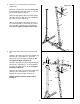
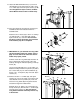
3. Press the 1 1/4” Inner Cap (57) into the Front Upright (42). 3 Single Hole 63 3 64 3 Attach the 1” Plastic Stop (64) to the centre hole in the Stop Bracket (63) with a 5/16” x 1 1/2” Bolt (24) and 5/16” Nylon Locknut (3). 24 8 57 Attach the Stop Bracket (63) to the Front Upright (42) with a 5/16” x 2” Bolt (61), 5/16” Flat Washer (8), and 5/16” Nylon Locknut (3). 61 Slide the Front Upright (42) onto the two 5/16” x 2 1/2” Carriage Bolts (1) in the Base (4).
5. Press two 1 1/2” Bushings (93) into the Left Pedal (90); press two 1 1/2” Bushings (93) into the Right Pedal (89). Attach a Pedal Cover (92) to each Pedal with a 1/2” Tap Screw (6). 5 92 6 92 6 89 Lubricate the pedal axles on the Rear Upright (82). Slide the Right and Left Pedals (89, 90) onto the right and left pedal axles. Note: Make sure that the Pedals are on the correct sides; the slotted brackets must be on the insides of the Pedals.
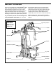
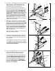
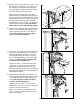
9. Press the Weight Tube Endcap (79) into the indicated end of the Weight Tube (80). 9 Upper Ends of Weight Guides have Holes Insert the Weight Tube (80) into the stack of Weights (25). Slide the tenth Weight (25) onto the upper end of the Weight Tube. The Weight Tube must be turned so the welded pin is in the pin groove in the Weight. 72 Locate the lower ends of the Weight Guides (72) (there are holes near the upper ends). Insert the lower ends of the Weight Guides into the ten Weights (25).
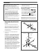
12. Press two 1 3/4” Inner Caps (44) into each of the Arms (46). 12 Apply lubricant to the lower axles on the Arm Frame (52). Slide an Arm (46) onto one of the axles. Hold two 1” Retainers (54) and a 1” Round Cover Cap (55) against the lower end of the axle. The teeth on the Retainers must bend toward the Round Cover Cap (see inset drawing). Tap the Retainers and Round Cover Cap onto the axle. 42 60 44 52—Lubricate Attach the other Arm (46) to the Arm Frame (52) in the same manner.
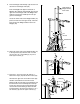
15. Attach the Wide Swivel Bracket (71) to the indicated bracket on the Top Frame (67) with a 5/16” x 3 1/4” Bolt (35) and 5/16” Nylon Locknut (3). Do not overtighten the Nylon Locknut; the Wide Swivel Bracket must be able to swivel freely. 15 35 67 3 16. If the parts shown at the right have not been preassembled, follow the instructions below to assemble them. 71 16 77 Attach the two “I” Plates (78) to two 4 1/2” Pulleys (77) with two 3/8” x 1 3/4” Bolts (48) and 3/8” Nylon Locknuts (21) as shown.
19. Remove the 3/8” Nylon Locknut (21), 3/8” x 1 3/4” Bolt (48), and 4 1/2” Pulley (77) from one end of the “I” Plates (78). Route the Long Cable (66) under the Pulley and reattach the Pulley to the “I” Plates with the Bolt and Nylon Locknut. 19 67 71 15 48 59 Refer to the inset drawing. (Note: The Wide Swivel Bracket [71] is attached to the Top Frame [67]; it is shown disassembled for clarity.) Lay the Long Cable (66) over a 3 1/2” Pulley (15).
23. Hold the indicated end of the Short Cable (23) under the 3 1/2” Pulley (15) on the Front Upright (42). Attach the 5/16” x 3 1/2” Bolt (87), two 5/16” Flat Washers (8), the 1” Metal Spacer (22), and a 5/16” Nylon Locknut (3) to the Front Upright as shown. Be sure that the Short Cable is between the Pulley and the Metal Spacer. Tighten the 3/8” Nylon Locknut (21) and 3/8” x 3 1/2” Bolt (not shown).
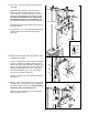
26. Press a 1 1/2” Inner Cap (32) into the Seat Frame (36). 26 Insert a 1/4” x 2” Carriage Bolt (38) into the centre of each Seat Plate (37). Attach the Seat Plates to the Seat (13) with four 1/4” x 3/4” Screws (18). 13 Wide End 37 38 Insert the two 1/4” x 2” Carriage Bolts (38) into the Seat Frame (36). Make sure that the Seat (13) is turned so the wide end is toward the 1 1/2” Inner Cap (32). Tighten a 1/4” Nylon Locknut (7) with 1/4” Flat Washer (10) onto each Carriage Bolt.
30. Attach a VKR Armrest (99) to the Right VKR Arm (101) with two 1/4” x 2” Screws (102) and 1/4” Flat Washers (10). 30 Attach a VKR Armrest (99) to the Left VKR Arm (100) in the same manner. 99 100 101 10 99 102 31. Insert a 7” Handle (47) into the Right VKR Arm (101). Attach the Handle with a 5/16” x 2” Bolt (61), two 5/16” Flat Washers (8), and a 5/16” Nylon Locknut (3). 31 Attach the other 7” Handle (47) to the Left VKR Arm (100) in the same manner. 47 61 100 3 32.
NOTES 14
ADJUSTMENT The instructions below describe how each part of the weight system can be adjusted. IMPORTANT: When attaching the lat bar or nylon strap, make sure that the attachments are in the correct starting position for the exercise to be performed. If there is any slack in the cable or chain as an exercise is performed, the effectiveness of the exercise will be reduced. CHANGING THE WEIGHT SETTING To change the weight setting, insert the Weight Pin (26) under one of the Weights (25).
ATTACHING THE LEG LEVER TO THE LOW PULLEY STATION To use the Leg Lever (29), the seat must be attached to the front upright (see ATTACHING AND REMOVING THE SEAT on page 15). 29 83 Attach the Chain (84) between the 5/16” x 2” Eyebolt (62) on the Leg Lever (29) and the Short Cable (23) with two Cable Clips (83). 62 23 84 ATTACHING THE LAT BAR OR NYLON STRAP TO THE HIGH PULLEY STATION 66 Attach the Lat Bar (85) to the Long Cable (66) with a Cable Clip (83).
WEIGHT RESISTANCE CHART WEIGHT PLATES PRESS ARM (lbs.) BUTTERFLY ARM (lbs.) LEG LEVER (lbs.) HIGH PULLEY (lbs.) LOW PULLEY (lbs.
TROUBLE-SHOOTING AND MAINTENANCE Inspect and tighten all parts each time you use the weight system. Replace any worn parts immediately. The weight system can be cleaned using a damp cloth and mild non-abrasive detergent. Do not use solvents. TIGHTENING THE CABLES 15 Woven cable, the type of cable used on the weight system, can stretch slightly when it is first used. If there is slack in the cables before resistance is felt, the cables should be tightened.
CABLE DIAGRAM The cable diagram below shows the proper routing of the Short Cable (23) and the Long Cable (66). Use the diagram to make sure that the two cables are assembled correctly. The letters show the routing of the Short Cable (23); the numbers show the routing of the Long Cable (66).
ORDERING REPLACEMENT PARTS If you encounter any difficulties or problems with this product, contact the ICON Fitness Lifestyle Ltd. office, or write: ICON Fitness Lifestyle Ltd. Greenwich House 223 North Street Sheepscar West Yorkshire Leeds LS7 2AA Tel: Country Code: 0345-089009 Fax: 113-241-1120 To help us assist you, please be prepared to give the following information: • The MODEL NUMBER of the product (WESY60400). • The NAME of the product (WEIDER® VIPER 2000).
REMOVE THIS PART IDENTIFICATION CHART FROM THE MANUAL! This chart is provided to help you identify the small parts used in assembly. Important: Some parts may have been pre-assembled for shipping purposes; if you cannot find a part in the parts bags, check to see if it has been pre-assembled.
1/4" Nylon Locknut (7)—6 1/2" Tap Screw (6)–2 5/16" Jam Nut (2)–2 1/4" x 3/4" Screw (18)–8 1/4" x 2" Screw (102)–4 5/16" Nylon Locknut (3)–30 1/4" x 2 1/2" Screw (43)–4 3/8" Nylon Locknut (21)–12 5/16" x 1 1/2" Bolt (24)–2 3/8" x 1 3/4" Bolt (48)–8 1/4" Flat Washer (10)–10 1/4" x 2" Carriage Bolt (38)–2 5/16" Flat Washer (8)–23 5/16" x 2" Bolt (61)–3 5/16" x 2 1/4" Bolt (33)–5 3/8" Flat Washer (9)–5 5/16" x 2 1/2" Carriage Bolt (1)–3
5/16" x 2 3/4" Carriage Bolt (14)–3 1/2" x 3/8" Spacer (51)—2 5/16" x 2 3/4" Bolt (11)–10 3/8" x 2 3/4" Bolt (70)–3 5/16" x 3" Bolt (17)–1 1/2" x 1/2" Spacer (65)—2 1/2" x 3/4" Spacer (73)—2 1" Metal Spacer (22)–1 1" Plastic Stop (64)–1 5/16" x 3 1/4" Bolt (35)–2 5/8" Retainer (95)–2 5/16" x 3 1/2" Bolt (87)–1 3/8" x 3 1/2" Bolt (16)–1 5/16" x 6" Bolt (74)–1 1" Retainer (54)–6
3/4" Round Inner Cap (34)–4 1" Round Inner Cap (49)–8 1" Round Cover Cap (55)–4 5/8" Round Cover Cap (96)–2 5/8" Spacer (97)–2 1 1/4" Inner Cap (57)—1 5/16" x 2" Eyebolt (62)—1 1 3/4" Inner Cap (44)–6 1 1/2" Inner Cap (32)—4 2" Inner Cap (27)–3 2" Outer Cap (88)–2
81 REMOVE THIS PART LIST/EXPLODED DRAWING FROM THE MANUAL!
PART LIST—Model No. WESY60400 Key No. Qty.
61 8 90 99 89 92 54 32 49 8 3 47 49 6 55 96 102 93 8 32 3 11 98 97 49 47 49 91 101 6 10 95 8 99 93 55 10 10 102 61 54 95 96 87 8 3 100 43 8 12 21 78 104 105 77 104 3 1 104 77 12 3 104 78 8 88 86 48 5 11 3 27 3 82 8 2 67 8 4 103 25 23 3 74 2 66 ?? 48 14 11 3 19 73 15 21 3 8 26 88 1 11 21 9 3 3 8 48 21 3 8 27 3 27 15 59 23 3 87 48 14 8 34 7 12 104 15 104 44 8 46 54 44 34 7 13 36 44 50