
User's Manual
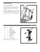

PART LIST/EXPLODED DRAWING—Model No. WEMC06740 R1204A
7
5
7
4
3
1
1
6
2
2
8
9
9
10
11
ADJUSTMENT
1 2 Gas Spring
2 2 Shank
3 1 Rear Top Endcap
4 1 Front Top Endcap
5
1 Front Bottom Endcap
6
1
Rear Bottom Endcap
7 4 Gas Spring End
8 1 Threaded Spacer
9 2 Button Bolt
10 1 Pin
11 1 Sensor Plate
# 1 User’s Manual
Key No. Qty. Description
Note: “#” indicates a non-illustrated part.
Specifications are subject to change without notice.
A
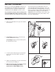
TTACHING THE POWER PAK
Set the
Threaded Spacer (8) onto the Power Pack
Frame (D). Insert the Pin (10) through the Side Mech
Cover (A), the Top Endcaps (3, 4), and the Mech
Frame (E).
Attaching the POWER PAK to your resistance system
will increase your minimum and maximum resistance
levels. The resistance system can be used at a lower
resistance level again by removing the POWER PAK.
3
4
A
E
D
8
10