Model No. WEEVSY87210 Serial No. Write the serial number in the space above for future reference. USER'S MANUAL Serial Number Decal QUESTIONS? As a manufacturer, we are committed to providing complete customer satisfaction. If you have questions, or if there are missing or damaged parts, please call: 08457 089 009 Or write: ICON Health & Fitness Ltd. Unit 4 Revie Road Industrial Estate Revie Road Beeston Leeds, LS11 8JG UK email: csuk@iconeurope.
TABLE OF CONTENTS IMPORTANT PRECAUTIONS . . . . . . . . . . . . . . . . . . . . . . . . . . . . . . . . . . . . . . . . . . . . . . . . . . . . . . . . . . . . .3 BEFORE YOU BEGIN . . . . . . . . . . . . . . . . . . . . . . . . . . . . . . . . . . . . . . . . . . . . . . . . . . . . . . . . . . . . . . . . . . .4 ASSEMBLY . . . . . . . . . . . . . . . . . . . . . . . . . . . . . . . . . . . . . . . . . . . . . . . . . . . . . . . . . . . . . . . . . . . . . . . . . . .5 HOW TO USE THE WEIGHT SYSTEM . . . .
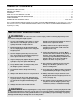
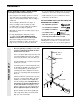
The decals shown below have been placed on the weight system in the locations shown. If decals are missing or illegible, please call our Customer Service Department to order free replacement decals (see the back cover of this manual). Apply the decals in the locations shown. ! WARNING • Misuse of this product may result in serious injury. • Read user’s manual and follow all warnings and operating instructions prior to use. • Do not allow children on or around machine.
BEFORE YOU BEGIN Thank you for selecting the versatile WEIDER® 8515 weight system. The WEIDER 8515 weight system offers a selection of weight stations designed to develop every major muscle group of the body. Whether your goal is to tone your body, build dramatic muscle size and strength, or improve your cardiovascular system, the WEIDER 8515 weight system will help you to achieve the specific results you want. questions, please call our Customer Service Department at 08457 089 009.
ASSEMBLY Before beginning assembly, carefully read the following information and instructions: • As you assemble the weight system, be sure that all parts are oriented as shown in the drawings. • Place all parts of the weight system in a cleared area and remove the packing materials; do not dispose of the packing materials until assembly is completed. • Tighten all parts as you assemble them, unless instructed to do otherwise.
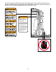
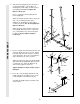
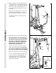
2. Slide the Front Upright (42) onto the 5/16” x 2 1/2” Carriage Bolts (1) in the Base (4). Hand tighten a 5/16” Nylon Locknut (3) onto each Carriage Bolt. Do not tighten the Nylon Locknuts yet. 2 Press a 1” Square Inner Cap (65) into the Front Upright (42). Attach the slotted end of the Brace (87) to the 5/16” x 2 1/2” Carriage Bolt (1) in the Stabiliser (5). Hand tighten a 5/16” Nylon Locknut (3) onto the Bolt. Do not tighten the Nylon Locknut yet.
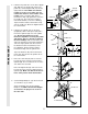
5. Lubricate the pedal axles on the Rear Upright (56). Slide the Left Pedal (79) onto the left pedal axle, and the Right Pedal (78) onto the right pedal axle. Note: Make sure that the Pedals are on the correct sides; the slotted brackets must be on the insides of the Pedals. Hold a 1" Retainer (69) and a 1" Round Cover Cap (70) against the end of the left pedal axle. The teeth on the Retainer must bend outward (see the inset drawing). Tap the Retainer and the Round Cover Cap onto the pedal axle.
9. Press the Weight Tube Bumper (64) into the end of the Weight Tube (63). Insert the Weight Tube into the stack of Weights (25). Be sure that the pins on the Weight Tube are sitting in the pin grooves in the top Weight. 9 Holes Lubricate the insides of the holes in the Top Weight (76). Set the Top Weight onto the stack of Weights (25). Insert both Weight Guides (62) into the stack of Weights. Be sure that the holes in the Weight Guides are at the top, as shown.
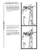
12. Wet the handle of one Press Arm (46) with soapy water. Slide a 5” Plastic Grip (31) onto the handle. Press a 1” Round Inner Cap (49) into the other end of the handle. Press a 1 3/4” Square Inner Cap (44) into the top of the Press Arm. 12 Attach the Press Arm (46) to one side of the Press Frame (17) with two 5/16” x 2 1/2” Bolts (22) and two 5/16” Nylon Locknuts (3). 44 31 Assemble the other Press Arm (46) in the same manner. 49 46 22 3 ARM ASSEMBLY 17 46 13.
As you assemble the cables and pulleys in steps 14 through 22, please refer to the CABLE DIAGRAM on page 22 of this manual. 14 23 55 CABLE ASSEMBLY 14. Route the Long Cable (23) around the 3 1/2” Pulley (15) attached to the Top Frame (55). Be sure that the end of the Cable with the ball is on the indicated side of the Pulley and that the Cable is between the Pulley and the hook on the Top Frame. Tighten the 3/8” x 3 3/4” Bolt (71) and the 3/8” Nylon Locknut (not shown). 15.
16. Route the Long Cable (23) around the “V”Pulley (6) on the Right Arm (48). Be sure that the Cable is in the groove of the “V”-Pulley and that the Long Cable Trap (50) is turned to hold the Cable in place. Tighten the 3/8” x 2 1/2” Bolt (7) and the 3/8” Nylon Locknut (not shown). 16 68 50 7 6 20 Route the Long Cable (23) around the 3 1/2” Pulley (15) attached to the Pulley Bracket (20).
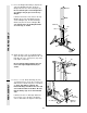
18. Route the Long Cable (23) around the 3 1/2” Pulley (15) attached to the bracket on the Top Frame (55). Tighten the 3/8” x 2” Bolt (12) and the 3/8” Nylon Locknut (21). (Note: This Pulley is pre-assembled. It has been shown disassembled for easy part identification.) Be sure that the Cable is in the groove of the Pulley and that the Cable and Pulley move smoothly. 18 23 55 12 Bracket 15 CABLE ASSEMBLY 21 19. Remove the 3 1/2” Low Pulley (88) from the Press Frame (17).
20. Route the Short Cable (58) around the 3 1/2” Pulley (15) attached to the upper hole in the Press Frame (17). Be sure that the Cable Trap (66) is in the “3 o’clock” position and that the Cable is routed around the Pulley as shown. Tighten the 3/8” Nylon Locknut (21) and the 3/8” x 3 3/4” Bolt (not shown). 20 42 If the indicated 3 1/2” Pulley (15) is preattached to the Front Upright (42), remove it. Route the Short Cable (58) around the 3 1/2” Pulley.
CABLE ASSEMBLY 22. Attach the Long Cable (23) to the Small “U”Bracket (67) with a 1/4” Nylon Locknut (2) and a 1/4” Washer (10). Do not completely tighten the Nylon Locknut. It should be threaded onto the end of the Cable so only a couple of threads are showing above the Nylon Locknut, as shown in the inset drawing. 22 23 Attach the Small “U”-Bracket (67) to the Weight Tube (63) with the 5/16” x 1 3/4” Bolt (72) and a 5/16” Nylon Locknut (3). 3 72 67 63 10 2 23 57 10 2 23.
25. Press a 1 1/2” Square Inner Cap (32) into the Leg Lever (29). 25 Lubricate the 5/16” x 2 1/4” Bolt (33). Attach the Leg Lever (29) to the Seat Frame (36) with the 5/16” x 2 1/4” Bolt and a 5/16” Nylon Locknut (3). 36 3 33—Lubricate 29 Insert the 3/8” x 2” Eyebolt (35) into the Leg Lever (29) from the direction shown. Tighten a 3/8” Nylon Locknut (21) with a 3/8” Washer (9) onto the Eyebolt. 8 35 32 26. Rest the Seat Frame (36) on the indicated pin in the Front Upright (42).
28. Make sure that all parts have been properly tightened. The use of the remaining parts will be explained in HOW TO USE THE WEIGHT SYSTEM, beginning on page 17. Before using the weight system, pull each cable a few times to be sure that the cables move smoothly over the pulleys. If one of the cables does not move smoothly, find and correct the problem. IMPORTANT: If the cables are not properly installed, they may be damaged when heavy weight is used.
HOW TO USE THE WEIGHT SYSTEM The instructions below describe how each part of the weight system can be adjusted. IMPORTANT: When attaching the lat bar or nylon strap, make sure that the attachments are in the correct starting position for the exercise to be performed. If there is any slack in the cables or chain as an exercise is performed, the effectiveness of the exercise will be reduced.
ATTACHING AND REMOVING THE SEAT 42 Set the bracket on the Seat Frame (36) onto the indicated pins on the Front Upright (42). Attach the Seat Frame to the Front Upright with the 5/16” x 2 3/4” Carriage Bolt (14) and the Seat Knob (40). 40 36 For some exercises, the Seat (13) must be removed. First, be sure that the chain is not attached to the leg lever. Next, remove the Seat Knob (40) and the 5/16” x 2 3/4” Carriage Bolt (14) from the Seat Frame (36). Lift the Seat Frame off the Front Upright (42).
LOCKING THE WEIGHT STACK When the weight system is not in use, the Lock Pin (90) and Lock (91) should be attached. Insert the Lock Pin through a Weight Guide (62). Attach the Lock to the Lock Pin.
WEIGHT RESISTANCE CHART This chart shows the approximate weight resistance at each station. “Top” refers to the 6.5-lb. top weight. The other numbers refer to the 12.5 lbs. weight plates. Weight resistance shown for the butterfly arm station is for each butterfly arm. Note: The actual resistance at each weight station may vary due to differences in individual weight plates, as well as friction between the cables, pulleys, and weight guides. WEIGHT PLATES PRESS ARM (lbs.) BUTTERFLY ARM (lbs.
TROUBLESHOOTING AND MAINTENANCE Inspect and tighten all parts often and replace any worn parts immediately. The weight system can be cleaned using a damp cloth and mild non-abrasive detergent. Do not use solvents. TIGHTENING THE CABLES 1 23 Woven cable, the type of cable used on the weight system, can stretch slightly when it is first used. If there is slack in the cables before resistance is felt, the cables should be tightened.
CABLE DIAGRAM The cable diagram below shows the proper routing of the Short Cable (58) and the Long Cable (23). Use the diagram to be sure that the two cables and the cable traps have been assembled correctly. If the cables have not been correctly routed, the weight system will not function properly and damage may occur. The numbers show the correct route for each cable. The starting and ending points of each cable are labelled. Be sure that the cable traps do not touch or bind the cables.
NOTES 23
ORDERING REPLACEMENT PARTS If you encounter any difficulties or problems with this product, contact the ICON Fitness Lifestyle Ltd. office, or write: ICON Health & Fitness Ltd.
REMOVE THIS PART IDENTIFICATION CHART FROM THE MANUAL This chart is provided to help you identify the small parts used in assembly. Important: Some parts may have been pre-assembled for shipping purposes. If you cannot find a part in the parts bags, check to see if it has been pre-assembled. IMPORTANT: Assembly is divided into four stages: 1) frame assembly, 2) arm assembly, 3) cable assembly, and 4) seat assembly. The hardware for each stage is packaged separately.
3/4" Round Inner Cap (34) 1" Round Inner Cap (49) 1" Round Cover Cap (70) 5/8" x 9/16" Spacer (73) 5/8" Round Cover Cap (85) 1/2" x 3/4" Spacer (61) 1" x 7/8" Plastic Bushing (75) 5/8" Spacer (86) 1 3/4" Square Inner Cap (44) 1" Square Inner Cap (65) 1 1/2" Square Inner Cap (32) 2" Square Inner Cap (27) 2" Square Outer Cap (51)
1/4" x 2" Carriage Bolt (38) 1/4" x 1/2" Screw (18) 1/2" Metal Screw (77) 5/16" Washer (8) 1/4" Washer (10) 5/16" x 2 3/4" Bolt (1 1) 5/16" x 2 1/2" Bolt (22) 5/16" x 1 3/4" Bolt (72) 1/4" x 2 1/2" Screw (43) 1/4" x 2" Machine Screw (24) 5/16" x 2 3/4" Carriage Bolt (14) 5/16" x 2 1/2" Carriage Bolt (1) 5/16" x 6" Bolt (60) 5/16" x 5" Bolt (68) 3/8" Nylon Locknut (21) 3/8" Nylon Jam Nut (92) 5/16" Nylon Locknut(3) 1/4" Nylon Locknut (2) 5/16" x 2" Eyebolt (35) 3/8" x 2 1/2" Bolt (7) 5/16
REMOVE THIS PART LIST/EXPLODED DRAWING FROM THE MANUAL 81 SAVE THIS PART LIST/EXPLODED DRAWING FOR FUTURE REFERENCE
PART LIST—Model No. WEEVSY87210 Key No. Qty.
31 69 54 70 82 57 2 10 21 78 89 89 77 83 31 82 84 12 85 58 15 69 79 81 80 86 70 77 83 21 39 84 20 55 81 85 15 66 53 3 3 12 68 51 11 52 87 1 5 3 56 31 3 27 14 2 10 8 3 8 11 3 21 91 67 60 55 19 4 61 3 64 63 21 9 1 26 25 92 51 90 3 76 43 10 72 3 44 49 15 12 62 23 8 11 42 21 50 44 6 15 27 3 65 7 71 41 23 89 45 44 48 70 69 89 71 15 74 6 7 50 40 14 21 36 34 30 10 46 49 24 35 2 13 44 34 38