
User's Manual


9
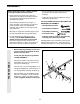
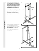
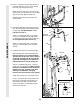
9. Attach the upper ends of the Short Weight
Guides (73) to the Top Frame (55) with a 5/16”
x 6” Bolt (60), two 1/2” x 3/4” Spacers (61), and
a 5/16” Nylon Locknut (3).
Attach the upper ends of the Long Weight
Guides (62) to the Top Frame (55) in the same
manner.
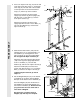
10. Locate and open the parts bag labelled
“ARM ASSEMBLY.”
Press one 2” Square Inner Cap (27) into the end
of the Leg Press Arm (96). Be sure there is a
Bushing (98) in each side of the Stabiliser (5).
Lubricate a 3/8” x 3 1/4” Bolt (67). Attach the
Leg Press Arm (96) to the Stabiliser (5) with the
Bolt and a 3/8” Nylon Locknut (21). Do not over-
tighten the Nylon Locknut; the Leg Press
Arm must be able to pivot freely.
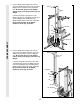
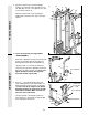
11. Press a 1” x 7/8” Plastic Bushing (90) onto
each welded spacer on the Press Frame (17).
Slide the Press Frame into place on the Base
(4). Note: This will be a tight fit. The Plastic
Bushings should fit on each end of the indi-
cated tube in the Base. Make sure that the
holes are on the side shown.
Lubricate the 3/8” x 8” Bolt (59). Attach the
Press Frame (17) to the Base (4) with the Bolt
and a 3/8” Nylon Locknut (21).
11
17
Holes must
be on this
side
59—Lubricate
Welded Spacers
21
4
Tube
90
9
10
FRAME ASSEMBLYARM ASSEMBLY
61
61
3
3
60
73
62
55
27
96
67—Lubricate
5
98
98
60
21