
User's Manual

18
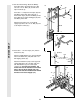
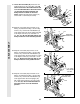
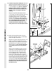
36. Slide a 5/16” Flat Washer (8) onto a 5/16” x 2
3/4” Bolt (11). Insert the Bolt through the indi-
cated hole in the Pivot Arm (101). The Bolt
must be inserted from the side shown.
Slide another 5/16” Flat Washer (8) onto the
Bolt. Fully tighten a 5/16” Nylon Jam Nut (93)
onto the Bolt.
Wrap the Military Press Cable (72) around a
3 1/2” Pulley (15). Attach the Pulley, a set of
Pulley Covers (114), and two 3/8” Flat Washer
(9) to the Pivot Arm (101) with a 3/8” x 3 3/4”
Bolt (88) and a 3/8” Nylon Jam Nut (112). Be
sure that the Pulley is on the side shown
and that the small tabs on the Pulley
Covers are in the position shown.
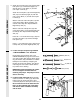
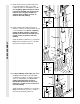
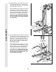
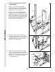
37. See inset drawing A. Wrap the Military Press
Cable (72) around a 3 1/2” Pulley (15). Attach
the Pulley and a set of Pulley Covers (114) to
the upper hole in a Long “U”-Bracket (57) with
a 3/8” x 2” Bolt (12) and a 3/8” Nylon Locknut
(21). Note: This may be pre-assembled. Be
sure that the small tabs on the Pulley
Covers are in the indicated location.
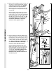
See inset drawing B. Slide the end of the
Military Press Cable (72) onto the end of the
5/16” x 2 3/4 Bolt (11) in the Pivot Arm (101).
Thread another 5/16” Nylon Jam Nut (93)
onto the Bolt. Do not fully tighten the sec-
ond Jam Nut. There must be room
between the two Jam Nuts for the end of
the Cable to pivot.
37
CABLE ASSEMBLY
72
114
21
57
A
B
12
15
114
Small tabs
should be up.
114
57
93
72
36
88
11
72
112
114
114
101
15
9
9
8
93
8
11
101
Small tabs
should be
here.