
User's Manual

15
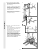
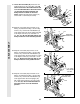
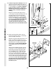
27. Locate the Low Cable (23). Route the Low
Cable under the 3 1/2” Low Pulley (102). Be
sure that the end of the Cable with the ball
is on the indicated side of the Press Frame
(17) and that the Cable is between the
Pulley and the crossbar on the Press
Frame. Tighten the 3/8” Nylon Locknut (21)
and the 3/8” x 3 3/4” Bolt (not shown).
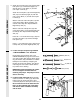
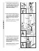
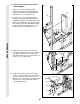
28. Wrap the Low Cable (23) around the 3 1/2”
Pulley (15). Attach the Pulley, a set of Pulley
Covers (114), and two 3/8” Flat Washers (9)
to the lower hole in the Front Upright (42) with
a 3/8” Nylon Jam Nut (112) and a 3/8” x 3
3/4” Bolt (88). Be sure the small tabs on the
Pulley Covers are in the indicated position.
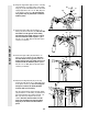
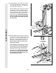
29. Wrap the Low Cable (23) around a 3 1/2”
Pulley (15). Attach the Pulley, a set of Pulley
Covers (114), and two 3/8” Flat Washers (9)
to the upper hole in the Press Frame (17) with
a 3/8” Nylon Locknut (21) and a 3/8” x 3 1/2”
Bolt (16). Be sure that the large tabs on the
Pulley Covers are in the position shown.
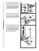
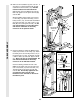
30. Wrap the Low Cable (23) around the 3 1/2”
Pulley (15). Attach the Pulley, a set of Pulley
Covers (114), and two 3/8” Flat Washers (9)
to the upper hole in the Front Upright (42)
with a 3/8” Nylon Jam Nut (112) and a 3/8” x
3 3/4” Bolt (88). Be sure the small tabs on
the Pulley Covers are in the indicated
position.
30
27
23
28
29
CABLE ASSEMBLY
21
17
Ball
23
112
9
Small tabs
should be here.
114—Small tabs
should be here.
88
9
15
42
114
23
15
42
112
9
88
9
23
9
16
17
114—Large
tabs should
be here.
15
102
Crossbar
9
21